STOLLMANN GMBH
TA+ X.24/V.35
|
Card Type |
ISDN TA |
|
Chip Set |
Unidentified |
|
Maximum Data Rate |
64Kbps x 2 |
|
Data Bus |
External |
|
Data Modulation Protocol |
V.110, 1TR6, DSS1, X.30 |
|
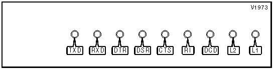
DIAGNOSTIC LED(S) | ||||
|
LED |
Color |
Status |
Condition | |
|
TXD |
Red |
On |
TA is transmitting data | |
|
TXD |
Red |
Off |
TA is not transmitting data | |
|
RXD |
Red |
On |
TA is receiving data | |
|
RXD |
Red |
Off |
TA is not receiving data | |
|
DTR |
Red |
On |
DTR signal is high | |
|
DTR |
Red |
Off |
DTR signal is low | |
|
DSR |
Red |
On |
DSR signal is high | |
|
DSR |
Red |
Off |
DSR signal is low | |
|
CTS |
Red |
On |
CTS signal is high | |
|
CTS |
Red |
Off |
CTS signal is low | |
|
RI |
Red |
Off |
Phone is not ringing | |
|
RI |
Red |
Blinking |
Phone is ringing | |
|
DCD |
Red |
On |
Carrier signal detected | |
|
DCD |
Red |
Off |
Carrier signal not detected | |
|
L2 Status |
L1 Status |
Condition | ||
|
On |
On |
TA is performing power-up tests or is connected | ||
|
Blinking |
Blinking |
TA is resetting | ||
|
Off |
On |
TA is ready | ||
|
.25s on, .75s off |
On |
Call is in progress | ||
|
.75s on, .25s off |
On |
Negotiation is in progress | ||
|
1s on, 1s off |
On |
No ISDN signal detected | ||
|
.5s on, .5s off |
On |
Remote TA busy | ||
|
.3s on, .3s off |
On |
Remote TA did not answer | ||
|
.25s on, .25s off |
On |
Could not connect to remote TA | ||
|
Off |
Off |
Hardware error detected | ||
|
Blinking |
Off |
Hardware error detected | ||
|
Off |
.25s on, .75s off |
ISDN has failed | ||
Proprietary AT Command Set
|
AUTO-ANSWER TIME | |
|
Type: |
Register |
|
Format: |
AT [cmds] S0=n [cmds] |
|
Default: |
Unidentified |
|
Range: |
0-24 |
|
Unit: |
5 seconds |
|
Description: |
Sets the amount of time that will elapse before the TA will answer an incoming call. When this value is set to 0 the TA will not automatically answer calls. A value of 1 will answer immediately. Values greater than 1 set the time to (n-1) * 5 seconds. |
|
CTS SIGNAL | ||
|
Type: |
Configuration | |
|
Format: |
AT [cmds] &Rn [cmds] | |
|
Description: |
Controls the operation of the Clear to Send signal. | |
|
Command |
Function | |
|
&R0 |
CTS follows RTS. | |
|
&R1 |
CTS forced high. | |
|
&R2 |
CTS follows V.110 flow control. | |
|
FLOW CONTROL MODE | ||
|
Type: |
Configuration | |
|
Format: |
AT [cmds] &Kn [cmds] | |
|
Description: |
Sets the type of flow control used. | |
|
Command |
Function | |
|
&K0 |
Flow control disabled. | |
|
&K3 |
CTS/RTS flow control enabled. | |
|
&K4 |
XON/XOFF flow control enabled. | |
|
&K5 |
Flow control disabled. | |
|
RESULT CODES | ||
|
Type: |
Register | |
|
Format: |
AT [cmds] S15=n [cmds] | |
|
Description: |
Enables caller ID information and extended result codes. | |
|
Command |
Function | |
|
S15=0 |
Caller ID information and extended result codes disabled. | |
|
S15=1 |
Caller ID information enabled. | |
|
S15=3 |
Caller ID information and extended result codes enabled. | |
|
BIT-MAPPED REGISTER S14 | |||||
|
Format: |
AT [cmds] S14=n [cmds] | ||||
|
Default: |
Unidentified | ||||
|
Range: |
0-14 | ||||
|
Description: |
Controls echo mode and result codes. | ||||
|
Bit |
Value |
Function | |||
|
0 |
0 |
Not used. | |||
|
1 |
0 1 |
Command echo disabled. Command echo enabled. | |||
|
2 |
0 1 |
Result codes enabled. Result codes disabled. | |||
|
3 |
0 1 |
Numerical result codes enabled. Verbose result codes enabled. | |||
Proprietary Command Set
|
COMMAND ECHOING | ||
|
Type: |
Configuration | |
|
Format: |
Jn | |
|
Description: |
Selects whether commands will be echoed back to the DTE. | |
|
Command |
Function | |
|
J0 |
Command echoing disabled. | |
|
í J1 |
Command echoing enabled. | |
|
CONNECTION SPEED | ||
|
Type: |
Configuration | |
|
Format: |
Hn | |
|
Description: |
Sets the speed of the remote connection. | |
|
Command |
Function | |
|
H1 |
Set speed to 300bps. | |
|
H2 |
Set speed to 600bps. | |
|
H3 |
Set speed to 1200bps. | |
|
H4 |
Set speed to 2400bps. | |
|
H5 |
Set speed to 4800bps. | |
|
í H6 |
Set speed to 9600bps. | |
|
H7 |
Set speed to 19.2Kbps. | |
|
H8 |
Set speed to 38.4Kbps. | |
|
CHANGE PROFILE CHANNEL | ||
|
Type: |
Configuration | |
|
Format: |
PROn | |
|
Description: |
Selects which channel’s profile is being edited. | |
|
Command |
Function | |
|
PRO1 |
Edit profile for channel 1. | |
|
PRO2 |
Edit profile for channel 2. | |
|
CTS SIGNAL - NO CONNECTION | ||
|
Type: |
Configuration | |
|
Format: |
NCTS 0xhh | |
|
Description: |
Controls the behaviour of the CTS signal when there is no ISDN connection. | |
|
Command |
Function | |
|
NCTS 0x01 |
CTS is forced low. | |
|
NCTS 0x02 |
CTS is forced high. | |
|
NCTS 0x04 |
CTS follows DTR. | |
|
NCTS 0x08 |
CTS follows RTS. | |
|
NCTS 0x10 |
CTS is forced high during connection and negotiation only. | |
|
NCTS 0x20 |
CTS follows remote DTR. | |
|
NCTS 0x40 |
CTS follows remote RTS. | |
|
NCTS 0x80 |
CTS follows V.110 flow control. | |
|
CTS SIGNAL - NEGOTIATION | ||
|
Type: |
Configuration | |
|
Format: |
WCTS 0xhh | |
|
Description: |
Controls the behaviour of the CTS signal while dialing and negotiating a connection. | |
|
Command |
Function | |
|
WCTS 0x01 |
CTS is forced low. | |
|
WCTS 0x02 |
CTS is forced high. | |
|
WCTS 0x04 |
CTS follows DTR. | |
|
WCTS 0x08 |
CTS follows RTS. | |
|
WCTS 0x10 |
CTS is forced high during connection and synchronization only. | |
|
WCTS 0x20 |
CTS follows remote DTR. | |
|
WCTS 0x40 |
CTS follows remote RTS. | |
|
WCTS 0x80 |
CTS follows V.110 flow control. | |
|
CTS SIGNAL - CONNECTION | ||
|
Type: |
Configuration | |
|
Format: |
CCTS 0xhh | |
|
Description: |
Controls the behaviour of the CTS signal while connected. | |
|
Command |
Function | |
|
CCTS 0x01 |
CTS is forced low. | |
|
CCTS 0x02 |
CTS is forced high. | |
|
CCTS 0x04 |
CTS follows DTR. | |
|
CCTS 0x08 |
CTS follows RTS. | |
|
CCTS 0x10 |
CTS is forced high during connection and synchronization only. | |
|
CCTS 0x20 |
CTS follows remote DTR. | |
|
CCTS 0x40 |
CTS follows remote RTS. | |
|
CCTS 0x80 |
CTS follows V.110 flow control. | |
|
DATA LENGTH | ||
|
Type: |
Configuration | |
|
Format: |
Ln | |
|
Description: |
Selects how many data bits will be transmitted. | |
|
Command |
Function | |
|
í L0 |
Synchronous mode. | |
|
L7 |
7 data bits. | |
|
L8 |
8 data bits. | |
|
DATA PARITY | ||
|
Type: |
Configuration | |
|
Format: |
Mn | |
|
Description: |
Selects how many parity bits will be transmitted. | |
|
Command |
Function | |
|
í M0 |
No parity. | |
|
M1 |
Odd parity. | |
|
M2 |
Even parity. | |
|
DATA STOP | ||
|
Type: |
Configuration | |
|
Format: |
Nn | |
|
Description: |
Selects how many stop bits will be transmitted. | |
|
Command |
Function | |
|
í M1 |
1 stop bit. | |
|
M2 |
2 stop bits. | |
|
DCD SIGNAL - NO CONNECTION | ||
|
Type: |
Configuration | |
|
Format: |
NDCD 0xhh | |
|
Description: |
Controls the behaviour of the DCD signal when there is no ISDN connection. | |
|
Command |
Function | |
|
NDCD 0x01 |
DCD is forced low. | |
|
NDCD 0x02 |
DCD is forced high. | |
|
NDCD 0x04 |
DCD follows DTR. | |
|
NDCD 0x08 |
DCD follows RTS. | |
|
NDCD 0x10 |
DCD is forced high during connection and negotiation only. | |
|
NDCD 0x20 |
DCD follows remote DTR. | |
|
NDCD 0x40 |
DCD follows remote RTS. | |
|
NDCD 0x80 |
DCD follows V.110 flow control. | |
|
DCD SIGNAL - NEGOTIATION | ||
|
Type: |
Configuration | |
|
Format: |
WDCD 0xhh | |
|
Description: |
Controls the behaviour of the DCD signal while dialing and negotiating a connection. | |
|
Command |
Function | |
|
WDCD 0x01 |
DCD is forced low. | |
|
WDCD 0x02 |
DCD is forced high. | |
|
WDCD 0x04 |
DCD follows DTR. | |
|
WDCD 0x08 |
DCD follows RTS. | |
|
WDCD 0x10 |
DCD is forced high during connection and synchronization only. | |
|
WDCD 0x20 |
DCD follows remote DTR. | |
|
WDCD 0x40 |
DCD follows remote RTS. | |
|
WDCD 0x80 |
DCD follows V.110 flow control. | |
|
DCD SIGNAL - CONNECTION | ||
|
Type: |
Configuration | |
|
Format: |
CDCD 0xhh | |
|
Description: |
Controls the behaviour of the DCD signal while connected. | |
|
Command |
Function | |
|
CDCD 0x01 |
DCD is forced low. | |
|
CDCD 0x02 |
DCD is forced high. | |
|
CDCD 0x04 |
DCD follows DTR. | |
|
CDCD 0x08 |
DCD follows RTS. | |
|
CDCD 0x10 |
DCD is forced high during connection and synchronization only. | |
|
CDCD 0x20 |
DCD follows remote DTR. | |
|
CDCD 0x40 |
DCD follows remote RTS. | |
|
CDCD 0x80 |
DCD follows V.110 flow control. | |
|
DEBUG PROFILE | |
|
Type: |
Immediate |
|
Format: |
TEST |
|
Description: |
Displays the profile editor debug page. |
|
DIAL MODE | ||
|
Type: |
Configuration | |
|
Format: |
En | |
|
Description: |
Selects the dial mode the TA will use. | |
|
Command |
Function | |
|
í E1 |
Manual dialing only; prompt for number will be displayed. | |
|
E2 |
Asynchronous V.25bis dial mode. | |
|
E3 |
Hotline dial mode; DTR is used for call signalling. | |
|
E4 |
Hotline dial mode; RTS is used for call signalling. | |
|
E5 |
Hotline dial mode; automatic dial attempt. | |
|
E6 |
Incoming calls only. | |
|
E7 |
Hayes dialing mode. | |
|
E8 |
Synchronous V.25bis dial mode. | |
|
DSR SIGNAL - NO CONNECTION | ||
|
Type: |
Configuration | |
|
Format: |
NDSR 0xhh | |
|
Description: |
Controls the behaviour of the DSR signal when there is no ISDN connection. | |
|
Command |
Function | |
|
NDSR 0x01 |
DSR is forced low. | |
|
NDSR 0x02 |
DSR is forced high. | |
|
NDSR 0x04 |
DSR follows DTR. | |
|
NDSR 0x08 |
DSR follows RTS. | |
|
NDSR 0x10 |
DSR is forced high during connection and negotiation only. | |
|
NDSR 0x20 |
DSR follows remote DTR. | |
|
NDSR 0x40 |
DSR follows remote RTS. | |
|
NDSR 0x80 |
DSR follows V.110 flow control. | |
|
DSR SIGNAL - NEGOTIATION | ||
|
Type: |
Configuration | |
|
Format: |
WDSR 0xhh | |
|
Description: |
Controls the behaviour of the DSR signal while dialing and negotiating a connection. | |
|
Command |
Function | |
|
WDSR 0x01 |
DSR is forced low. | |
|
WDSR 0x02 |
DSR is forced high. | |
|
WDSR 0x04 |
DSR follows DTR. | |
|
WDSR 0x08 |
DSR follows RTS. | |
|
WDSR 0x10 |
DSR is forced high during connection and synchronization only. | |
|
WDSR 0x20 |
DSR follows remote DTR. | |
|
WDSR 0x40 |
DSR follows remote RTS. | |
|
WDSR 0x80 |
DSR follows V.110 flow control. | |
|
DSR SIGNAL - CONNECTION | ||
|
Type: |
Configuration | |
|
Format: |
CDSR 0xhh | |
|
Description: |
Controls the behaviour of the DSR signal while connected. | |
|
Command |
Function | |
|
CDSR 0x01 |
DSR is forced low. | |
|
CDSR 0x02 |
DSR is forced high. | |
|
CDSR 0x04 |
DSR follows DTR. | |
|
CDSR 0x08 |
DSR follows RTS. | |
|
CDSR 0x10 |
DSR is forced high during connection and synchronization only. | |
|
CDSR 0x20 |
DSR follows remote DTR. | |
|
CDSR 0x40 |
DSR follows remote RTS. | |
|
CDSR 0x80 |
DSR follows V.110 flow control. | |
|
DTE/DCE MODE | ||
|
Type: |
Configuration | |
|
Format: |
Sn | |
|
Description: |
Sets whether the TA will operate as a DTE or a DCE device. | |
|
Command |
Function | |
|
í S0 |
TA will operate as DCE. | |
|
S1 |
TA will operate as DTE. | |
|
DTR SIGNAL | ||
|
Type: |
Configuration | |
|
Format: |
Dn | |
|
Description: |
Controls the operation of the Data Terminal Ready signal. | |
|
Command |
Function | |
|
D0 |
Incoming calls accepted regardless of DTR state; low DTR does not disconnect. | |
|
í D1 |
Incoming calls accepted only if DTR is high; DTR or RTS transition to high will initiate a hotline call if in hotline mode; low DTR disconnects. | |
|
D2 |
Incoming calls accepted only if DTR is high; high DTR or RTS will initiate a hotline call if in hotline mode; low DTR disconnects. | |
|
D3 |
Incoming calls accepted regardless of DTR state; DTR or RTS transition to high will initiate a hotline call if in hotline mode; low DTR disconnects. | |
|
D4 |
Incoming calls accepted regardless of DTR state; high DTR or RTS will initiate a hotline call if in hotline mode; low DTR disconnects. | |
|
D5 |
Incoming calls accepted only if DTR is high; DTR or RTS transition to high will initiate a hotline call if in hotline mode; low DTR does not disconnect. | |
|
D6 |
Incoming calls accepted only if DTR is high; high DTR or RTS will initiate a hotline call if in hotline mode; low DTR does not disconnect. | |
|
EAZ | ||
|
Type: |
Configuration | |
|
Format: |
An | |
|
Description: |
Sets which incoming calls are answered. | |
|
Command |
Function | |
|
A0 |
All incoming calls are answered; all channels are notified of the call. | |
|
A1 - A8 |
Only calls with a matching EAZ are answered. | |
|
A9 |
All incoming calls are answered; only the channel matching the EAZ is notified of the call. | |
|
EAZ - EDITOR | ||
|
Type: |
Configuration | |
|
Format: |
Tn | |
|
Description: |
Sets which incoming calls should be routed for remote configuration. | |
|
Command |
Function | |
|
T0 |
Only calls ending in "e" are routed to the editor. | |
|
T1 - T8 |
Only calls with a matching EAZ are answered. | |
|
T9 |
Calls matching the EAZ or ending in "e" are routed to the editor. | |
|
ENTER PROFILE EDITOR | ||
|
Type: |
Immediate | |
|
Description: |
Enters the profile editor so that changes may be made. | |
|
Mode |
Command | |
|
Manual dial |
<CR><ESC> | |
|
V.25bis dial |
<CR><ESC> | |
|
Hayes dial |
AT <CR><ESC> | |
|
All other modes |
Push reset button, then <CR><CR><ESC><ESC> | |
|
EXIT PROFILE EDITOR | |
|
Type: |
Immediate |
|
Format: |
EXIT <ESC> |
|
Description: |
Quits the editor without saving changes. |
|
FLOW CONTROL MODE - DCE | ||
|
Type: |
Configuration | |
|
Format: |
Bn | |
|
Description: |
Sets the type of flow control used. | |
|
Command |
Function | |
|
B0 |
Flow control disabled. | |
|
í B1 |
XON/XOFF flow control enabled. | |
|
B2 |
CTS flow control enabled. | |
|
FLOW CONTROL MODE - DTE | ||
|
Type: |
Configuration | |
|
Format: |
Cn | |
|
Description: |
Sets the type of flow control used. | |
|
Command |
Function | |
|
C0 |
Flow control disabled. | |
|
í C1 |
XON/XOFF flow control enabled. | |
|
C2 |
RTS flow control enabled. | |
|
C3 |
DTR flow control enabled. | |
|
HOTLINE NUMBER | |
|
Type: |
Configuration |
|
Format: |
HOT <#> |
|
Description: |
Sets the number for hotline calling. If no number is given, hotline calling will not be allowed. |
|
INACTIVITY TIMER | |
|
Type: |
Configuration |
|
Format: |
Fn |
|
Default: |
0 |
|
Range: |
0 - 60 |
|
Unit: |
1 minute |
|
Description: |
Sets the amount of time that there must be no activity on the ISDN line before the TA disconnects. |
|
INCOMING CALL NUMBER | |
|
Type: |
Configuration |
|
Format: |
RUFn <#> |
|
Description: |
Sets the number in position n of allowed incoming calls. |
|
LANGUAGE | ||
|
Type: |
Configuration | |
|
Format: |
Kn | |
|
Description: |
Selects the language the TA will display messages in. | |
|
Command |
Function | |
|
K0 |
Messages will be displayed in English. | |
|
í K1 |
Messages will be displayed in German. | |
|
LINE TYPE | ||
|
Type: |
Configuration | |
|
Format: |
Rn | |
|
Description: |
Sets the type of line the TA will be operating on. | |
|
Command |
Function | |
|
í R0 |
ISDN with BRI service. | |
|
R1 |
Group 3 leased line service with 1TR6. | |
|
R2 |
Group 2 leased line, 2B+D or B+D. | |
|
R3 |
Group 0 leased line, single B channel only. | |
|
R4 |
Point-to-point switched line. | |
|
R5 |
Point-to-point group 3 leased line with 1TR6. | |
|
LLC - INCOMING | ||
|
Type: |
Configuration | |
|
Format: |
Pn | |
|
Description: |
Sets the use of LLC for incoming DSS1 calls. | |
|
Command |
Function | |
|
P1 |
Only calls with matching LLC will be answered. | |
|
í P2 |
Ignore LLC when answering calls. | |
|
P3 |
All data calls will be answered. | |
|
P4 |
All calls will be answered. | |
|
LLC - OUTGOING | ||
|
Type: |
Configuration | |
|
Format: |
On | |
|
Description: |
Sets the use of LLC for outgoing DSS1 calls. | |
|
Command |
Function | |
|
O1 |
Standard LLC enabled. | |
|
í O2 |
LLC disabled. | |
|
O3 |
User-defined LLC enabled. | |
|
LLC - USER-DEFINED DATA OCTET | |
|
Type: |
Configuration |
|
Format: |
LLC=hh hh hh.. |
|
Description: |
Sets the user-defined LLC octets in hexadecimal. |
|
LOAD FIRMWARE | |
|
Type: |
Immediate |
|
Format: |
LOAD |
|
Description: |
Begins an XMODEM transfer to receive a firmware update. |
|
LOCAL SERIAL PORT SPEED | ||
|
Type: |
Configuration | |
|
Format: |
Gn | |
|
Description: |
Sets the speed of the serial port. | |
|
Command |
Function | |
|
G1 |
Set speed to 300bps. | |
|
G2 |
Set speed to 600bps. | |
|
G3 |
Set speed to 1200bps. | |
|
G4 |
Set speed to 2400bps. | |
|
G5 |
Set speed to 4800bps. | |
|
í G6 |
Set speed to 9600bps. | |
|
G7 |
Set speed to 19.2Kbps. | |
|
G8 |
Set speed to 38.4Kbps. | |
|
LOCK SERIAL PORT SPEED | ||
|
Type: |
Configuration | |
|
Format: |
In | |
|
Description: |
Selects whether the serial port speed will be adjusted to the DTE speed. | |
|
Command |
Function | |
|
I0 |
Serial port speed locked. | |
|
í I1 |
Serial port speed will match DTE speed. | |
|
MSN | |
|
Type: |
Configuration |
|
Format: |
MALL <#>*n |
|
Description: |
Sets the MSN and subaddress for the TA and the editor. |
|
MSN - TA | |
|
Type: |
Configuration |
|
Format: |
MTA1 <#>*n |
|
Description: |
Sets the MSN and subaddress for the TA. |
|
MSN - EDITOR | |
|
Type: |
Configuration |
|
Format: |
MED1 <#>*n |
|
Description: |
Sets the MSN and subaddress for the editor. |
|
NEXT PAGE | |
|
Type: |
Immediate |
|
Format: |
NEXT |
|
Description: |
Shows the next page of values. |
|
PREVIOUS PAGE | |
|
Type: |
Immediate |
|
Format: |
PREV |
|
Description: |
Shows the previous page of values. |
|
REMOTE CONFIGURATION PASSWORD | |
|
Type: |
Configuration |
|
Format: |
PWD xxxx |
|
Description: |
Sets the password for remote configuration. If no password is given, no password will be required. |
|
RESET TA | |
|
Type: |
Immediate |
|
Format: |
FRES |
|
Description: |
Resets the TA to its power-on state. |
|
RESET TO FACTORY DEFAULTS | |
|
Type: |
Immediate |
|
Format: |
DEFA |
|
Description: |
Resets all settings to their factory defaults. |
|
SAVE PROFILE | |
|
Type: |
Immediate |
|
Format: |
SAVE |
|
Description: |
Saves the current settings into the profile and quits the editor. |
|
SERVICE INDICATOR | ||
|
Type: |
Configuration | |
|
Format: |
Pn | |
|
Description: |
Sets the 1TR6 Service Indicator. | |
|
Command |
Function | |
|
í P0 |
Service Indicator reports standard line. | |
|
P1 |
Service Indicator reports Private SI. | |
|
P2 |
Service Indicator reports Private 2. | |
|
SERVICE INDICATOR DETAILS | |||
|
Type: |
Configuration | ||
|
Format: |
On | ||
|
Description: |
Sets the details for the 1TR6 Service Indicator. | ||
|
Pn Setting |
Command |
Function | |
|
P0 |
í O1 |
Service Indicator reports 1TR6. | |
|
O2 |
Service Indicator reports X.21. | ||
|
O3 |
Service Indicator reports AOI synch/asynch mode. | ||
|
P1 |
í O1 |
Service Indicator reports V.24 asynch. | |
|
O2 |
Service Indicator reports 64Kbps asynch. | ||
|
O3 |
Service Indicator reports V.24 BTX. | ||
|
O4 |
Service Indicator reports V.24 Text. | ||
|
O5 |
Service Indicator reports 64Kbps PC-Net. | ||
|
P2 |
í O1 |
Service Indicator reports Private 2 LLC with the data octet equal to 0. | |
|
O2 |
Service Indicator reports Private 2 LLC with the data octet not equal to 0. | ||
|
O3 |
Service Indicator reports Private 2 with the data octet equal to 0. | ||
|
SYNCHRONOUS SPEED | ||
|
Type: |
Configuration | |
|
Format: |
Qn | |
|
Description: |
Selects what data rate the TA will operate in when in synchronous mode. | |
|
Command |
Function | |
|
Q0 |
Use V.24 asynchronous mode. | |
|
Q1 |
Use data rate set with Gn and Hn. | |
|
í Q2 |
Use 64Kbps data rate. | |
|
Q3 |
Use 56Kbps data rate. | |
|
Q4 |
Use 48Kbps data rate. | |
|
UPDATE PROFILE | |
|
Type: |
Immediate |
|
Format: |
UPDA |
|
Description: |
Saves the current settings into the profile. |