PATTON ELECTRONICS COMPANY
1035
|
Card Type |
Short Range Modem |
|
Chip Set |
Unidentified |
|
I/O Options |
25-pin serial port (RS-232), power network interface via RJ-45 (RJ-11 optional) |
|
Wiring Type |
Unshielded twisted pair |
|
Maximum Data Rate |
64Kbps |
|
Data Bus |
External |
|
CONNECTIONS | ||||||
|
Function |
Label |
Function |
Label | |||
|
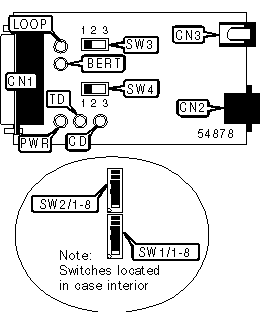
DTE/DCE serial port (25-pin connector) |
CN1 |
Power connector |
CN3 | |||
|
Network interface via RJ-45 connector |
CN2 | |||||
|
USER CONFIGURABLE SETTINGS | ||
|
Setting |
Label |
Position |
|
í Modem responds to local analog loopback requests from DTE pin 18 |
SW1/1 |
On |
|
Modem ignores LAL requests from DTE pin 18 |
SW1/1 |
Off |
|
í Modem responds to remote digital loopback requests from DTE pin 18 |
SW1/2 |
On |
|
Modem ignores RDL requests from DTE pin 18 |
SW1/2 |
Off |
|
í Factory configured - do not alter |
SW1/3 |
Off |
|
í Factory configured - do not alter |
SW1/4 |
Off |
|
í Factory configured - do not alter |
SW1/5 |
Off |
|
í Factory configured - do not alter |
SW1/6 |
Off |
|
í Factory configured - do not alter |
SW1/7 |
Off |
|
í V.54 test functions enabled |
SW1/8 |
Off |
|
V.54 test functions disabled |
SW1/8 |
On |
|
í Carrier forced high |
SW2/6 |
Off |
|
Carrier controlled by RTS |
SW2/6 |
On |
|
DATA RATE | ||||||
|
Setting |
SW2/1 |
SW2/2 |
SW2/3 | |||
|
32Kbps |
Off |
Off |
On | |||
|
í 56Kbps |
Off |
On |
Off | |||
|
64Kbps |
On |
Off |
Off | |||
|
TRANSMIT CLOCK SOURCE | ||
|
Source |
SW2/4 |
SW2/5 |
|
í Transmit clock generated internally |
On |
On |
|
Transmit clock derived from receive line signal |
Off |
On |
|
Transmit clock derived from terminal interface |
On |
Off |
|
RTS/CTS DELAY | ||
|
Setting |
SW2/7 |
SW2/8 |
|
í 7ms delay |
On |
On |
|
53ms delay |
On |
Off |
|
No delay |
Off |
Off |
|
LOOPBACK TEST SELECTOR | ||
|
Function |
Label |
Position |
|
Remote digital loopback initiated |
SW3 |
1 |
|
Normal operation. Loopback not activated |
SW3 |
2 |
|
Activates local analog loopback |
SW3 |
3 |
|
TEST PATTERN GENERATOR | ||
|
Function |
Label |
Position |
|
511/E test pattern transmitted (intentional errors inserted) |
SW4 |
1 |
|
Normal operation. Test pattern not activated |
SW4 |
2 |
|
511 test pattern transmitted |
SW4 |
3 |
|
DIAGNOSTIC LED(S) | |||
|
LED |
Color |
Status |
Condition |
|
PWR |
Green |
On |
Power is on |
|
PWR |
Green |
Off |
Power is off |
|
TD |
Red |
On |
Modem detecting zero on transmit data |
|
TD |
Red |
Off |
Modem not detecting zero on transmit data |
|
CD |
Red |
On |
Carrier signal high |
|
CD |
Red |
Off |
Carrier signal low |
|
BERT |
Red |
On |
Bit error likely in received signal or error detected in 511 or 511/E test pattern |
|
BERT |
Red |
Off |
Error not detected |
|
LOOP |
Red |
On |
Device has been placed in LAL or RDL test mode by local or remote user |
|
LOOP |
Red |
Off |
Device is not conducting a test |