PENRIL DATABILITY NETWORKS
ALLIANCE V.32/19.2, ALLIANCE V.32/19.2M
|
Modem Type |
Data (synchronous/asynchronous)/Fax |
|
Maximum Data Rate |
19.2Kbps |
|
Maximum Fax Rate |
14.4Kbps |
|
Data Bus |
External |
|
Fax Class |
Class I & II |
|
Data Modulation Protocol |
Bell 103A/212A, 208A/B ITU-T V.21, V.22, V.22bis, V.26, V.26bis V.27bis, V.27ter V.29,V.32, V.32bis, V.33 AT&T V.32terbo |
|
Fax Modulation Protocol |
ITU-T V.17, V.27ter, V.29 |
|
Error Correction/Compression |
MNP5, V.42, V.42bis |
|
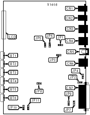
CONNECTIONS | |||
|
Purpose |
Location |
Purpose |
Location |
|
LCD display |
LCD |
Line in |
CN1 |
|
Left arrow button |
BT1 |
Leased line out |
CN2 |
|
1 button |
BT2 |
Leased line out |
CN3 |
|
2 button |
BT3 |
Switched line out |
CN4 |
|
3 button |
BT4 |
DC power |
CN5 |
|
Right arrow button |
BT5 |
Diagnostic connector |
CN6 |
|
ENTER button |
BT6 |
RS-232/422 |
CN7 |
|
A/A1 - MI/MIC CONTROL | ||
|
Control Type |
JP5 |
JP6 |
| » A/A1 control. |
Pin 1 & 2 closed. |
Pin 1 & 2 closed. |
|
MI/MIC control. |
Pin 2 & 3 closed. |
Pin 2 & 3 closed. |
|
DTE CONNECTOR - PIN 25 | |
|
Function |
JP7 |
|
Analog loopback (Input). |
Pin 1 & 2 closed. |
| » Test Mode Indicator (Output). |
Pin 2 & 3 closed. |
|
FRAME/SIGNAL GROUND | |
|
Ground Type |
JP1 |
|
Frame and signal ground connected. |
Pin 1 & 2 closed. |
| » Frame and signal ground not connected. |
Pin 2 & 3 closed. |
|
FACTORY CONFIGURED SETTINGS - DO NOT ALTER | |
|
Jumper |
Setting |
|
JP8 |
Pin 2 & 3 closed. |
|
JP9 |
Pin 2 & 3 closed. |
|
JP10 |
Pin 2 & 3 closed. |
|
JP11 |
Pin 2 & 3 closed. |
|
POWER | |||
|
Power Source |
JP2 |
JP3 |
JP4 |
| » AC power. |
Pin 1 & 2 closed. |
Pin 1 & 2 closed. |
Pin 1 & 2 closed. |
|
DC power. |
Pin 2 & 3 closed. |
Pin 2 & 3 closed. |
Pin 2 & 3 closed. |
Proprietary AT Command Set
See document V1409 for a full command summary.