MAXTECH CORPORATION
XPVS56I
|
Card Type |
Modem (asynchronous) |
|
Chipset |
Unidentified |
|
I/O Options |
Voice, speakerphone, microphone in, speaker out |
|
Maximum Data Rate |
56Kbps |
|
Maximum Fax Rate |
14.4Kbps |
|
Data Modulation |
Bell 103A/212A ITU-T V.21, V.22, V.22bis, V.23, V.32, V.32bis, V.34 U.S. Robotics x2 |
|
Fax Modulation |
ITU-T V.17, V.21CH2, V.27ter, V.29 |
|
Error Correction/Compression |
MNP5, V.42, V.42bis |
|
Fax Class |
Class I & II |
|
Data Bus |
8-bit ISA |
|
Card Size |
Full height, one-third length |
|
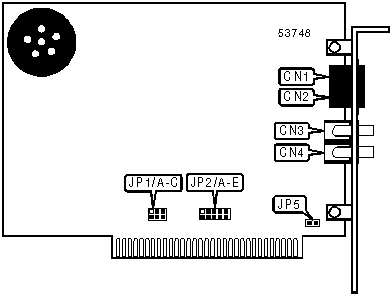
CONNECTIONS | |||
|
Function |
Label |
Function |
Label |
|
Telephone line out |
CN1 |
Microphone in or speaker out |
CN3 |
|
Telephone line in |
CN2 |
Microphone in or speaker out |
CN4 |
Note: It is not known which of CN3 and CN4 is the microphone in jack and which is the speaker out jack. | |||
|
USER CONFIGURABLE SETTINGS | ||
|
Setting |
Label |
Position |
|
í Plug-N-Play disabled |
JP1/C |
Closed |
|
Plug-N-Play enabled |
JP1/C |
Open |
|
Speakers attached to CN4 are stereo |
JP5 |
Closed |
|
Speakers attached to CN4 are mono |
JP5 |
Open |
Note: When JP1/C is set for Plug-N-Play mode, all other applicable settings must also be set for Plug-N-Play mode. | ||
|
SERIAL PORT ADDRESS SELECTION | ||
|
Setting |
JP1/A |
JP1/B |
|
3F8h (COM1:) |
Closed |
Closed |
|
í 2E8h (COM2:) |
Open |
Closed |
|
3F8h (COM3:) |
Closed |
Open |
|
2E8h (COM4:) |
Open |
Open |
|
Plug-N-Play |
Open |
Open |
|
INTERRUPT SELECTION | |||||
|
Setting |
JP2/A |
JP2/B |
JP2/C |
JP2/D |
JP2/E |
|
2 |
Closed |
Open |
Open |
Open |
Open |
|
í 3 |
Open |
Closed |
Open |
Open |
Open |
|
4 |
Open |
Open |
Closed |
Open |
Open |
|
5 |
Open |
Open |
Open |
Closed |
Open |
|
7 |
Open |
Open |
Open |
Open |
Closed |
|
Plug-N-Play |
Open |
Open |
Open |
Open |
Open |
|
SUPPORTED STANDARD COMMANDS |
|
Basic AT Commands |
|
+++, ‘comma’, A/ |
|
A, B, E, F, H, L, M, O, P, T, V, X, Z |
|
&C, &D, &F, &G, &P, &R, &S, &T, &W |
|
S-Registers |
|
S0, S1, S2, S3, S4, S5, S6, S7, S8, S9, S10, S11, S12, S18, S25 |
Note: See MHI help file for complete information. |
|
UNIDENTIFIED COMMANDS | |
|
Command |
Default |
|
S13 |
0 |
|
S15 |
0 |
|
S16 |
0 |
|
S27 |
0 |
|
S32 |
0 |
|
S33 |
0 |
|
S34 |
0 |
Proprietary AT Command Set
|
BREAK LENGTH | |
|
Type: |
Register |
|
Format: |
AT [cmds] S21=n [cmds] |
|
Default: |
10 |
|
Range: |
0 - 255 |
|
Unit: |
10 ms |
|
Description: |
Sets the length of the breaks sent from modem to the DTE when in error correction mode . |
|
BREAK TYPE | |
|
Type: |
Configuration |
|
Format: |
AT [cmds] &Yn [cmds] |
|
Description: |
Configures action of break signal. |
|
Command |
Function |
|
&Y0 |
Break empties buffer. |
|
í &Y1 |
Break empties buffer and is sent immediately. |
|
&Y2 |
Break does not empty buffer and is sent immediately. |
|
COMPRESSION MODE | |
|
Type: |
Configuration |
|
Format: |
AT [cmds] &Kn [cmds] |
|
Description: |
Selects the type of data compression that will be used. |
|
Command |
Function |
|
&K0 |
Data compression disabled. |
|
í &K1 |
Auto-detect compression mode. |
|
&K2 |
Data compression enabled. |
|
&K3 |
MNP5 data compression only enabled. |
|
CONNECTION SPEED LOWER LIMIT | |
|
Type: |
Configuration |
|
Format: |
AT [cmds] &Un [cmds] |
|
Description: |
Sets slowest allowed connection speed if &N is set to 1 or higher. |
|
Command |
Function |
|
&U0 |
No minimum connect speed. |
|
&U1 |
Set minimum connect speed to 300bps. |
|
&U2 |
Set minimum connect speed to 1200bps. |
|
&U3 |
Set minimum connect speed to 2400bps. |
|
&U4 |
Set minimum connect speed to 4800bps. |
|
&U5 |
Set minimum connect speed to 7200bps. |
|
&U6 |
Set minimum connect speed to 9600bps. |
|
&U7 |
Set minimum connect speed to 12Kbps. |
|
&U8 |
Set minimum connect speed to 14.4Kbps. |
|
&U9 |
Set minimum connect speed to 16.8Kbps. |
|
CONNECTION SPEED LOWER LIMIT (CON'T) | |
|
Command |
Function |
|
&U10 |
Set minimum connect speed to 19.2Kbps. |
|
&U11 |
Set minimum connect speed to 21.6Kbps. |
|
&U12 |
Set minimum connect speed to 24Kbps. |
|
&U13 |
Set minimum connect speed to 26.4Kbps. |
|
&U14 |
Set minimum connect speed to 28.8Kbps. |
|
&U15 |
Set minimum connect speed to 31.2Kbps. |
|
&U16 |
Set minimum connect speed to 33.6Kbps. |
|
&U17 |
Set minimum connect speed to 33.3Kbps. |
|
&U18 |
Set minimum connect speed to 37.3Kbps. |
|
&U19 |
Set minimum connect speed to 41.3Kbps. |
|
&U20 |
Set minimum connect speed to 42.6Kbps. |
|
&U21 |
Set minimum connect speed to 44Kbps. |
|
&U22 |
Set minimum connect speed to 45.3Kbps. |
|
&U23 |
Set minimum connect speed to 46.6Kbps. |
|
&U24 |
Set minimum connect speed to 48Kbps. |
|
&U25 |
Set minimum connect speed to 49.3Kbps. |
|
&U26 |
Set minimum connect speed to 50.6Kbps. |
|
&U27 |
Set minimum connect speed to 52Kbps. |
|
&U28 |
Set minimum connect speed to 53.3Kbps. |
|
&U29 |
Set minimum connect speed to 54.6Kbps. |
|
&U30 |
Set minimum connect speed to 56Kbps. |
|
&U31 |
Set minimum connect speed to 57.3Kbps. |
|
CONNECTION SPEED UPPER LIMIT | |
|
Type: |
Configuration |
|
Format: |
AT [cmds] &Nn [cmds] |
|
Description: |
Sets required connection speed if &U is set to 0; otherwise, sets fastest allowed connection speed. |
|
Command |
Function |
|
&N0 |
No maximum connect speed. |
|
&N1 |
Set maximum connect speed to 300bps. |
|
&N2 |
Set maximum connect speed to 1200bps. |
|
&N3 |
Set maximum connect speed to 2400bps. |
|
&N4 |
Set maximum connect speed to 4800bps. |
|
&N5 |
Set maximum connect speed to 7200bps. |
|
&N6 |
Set maximum connect speed to 9600bps. |
|
&N7 |
Set maximum connect speed to 12Kbps. |
|
&N8 |
Set maximum connect speed to 14.4Kbps. |
|
&N9 |
Set maximum connect speed to 16.8Kbps. |
|
&N10 |
Set maximum connect speed to 19.2Kbps. |
|
&N11 |
Set maximum connect speed to 21.6Kbps. |
|
&N12 |
Set maximum connect speed to 24Kbps. |
|
&N13 |
Set maximum connect speed to 26.4Kbps. |
|
&N14 |
Set maximum connect speed to 28.8Kbps. |
|
CONNECTION SPEED UPPER LIMIT (CON'T) | |
|
Command |
Function |
|
&N15 |
Set maximum connect speed to 31.2Kbps. |
|
&N16 |
Set maximum connect speed to 33.6Kbps. |
|
&N17 |
Set maximum connect speed to 33.3Kbps. |
|
&N18 |
Set maximum connect speed to 37.3Kbps. |
|
&N19 |
Set maximum connect speed to 41.3Kbps. |
|
&N20 |
Set maximum connect speed to 42.6Kbps. |
|
&N21 |
Set maximum connect speed to 44Kbps. |
|
&N22 |
Set maximum connect speed to 45.3Kbps. |
|
&N23 |
Set maximum connect speed to 46.6Kbps. |
|
&N24 |
Set maximum connect speed to 48Kbps. |
|
&N25 |
Set maximum connect speed to 49.3Kbps. |
|
&N26 |
Set maximum connect speed to 50.6Kbps. |
|
&N27 |
Set maximum connect speed to 52Kbps. |
|
&N28 |
Set maximum connect speed to 53.3Kbps. |
|
&N29 |
Set maximum connect speed to 54.6Kbps. |
|
&N30 |
Set maximum connect speed to 56Kbps. |
|
&N31 |
Set maximum connect speed to 57.3Kbps. |
|
DIAL | |
|
Type: |
Immediate |
|
Format: |
AT [cmds] D <#>;[cmds] |
|
Description: |
Dials the telephone number indicated according to any modifiers included in the string. |
|
Command |
Function |
|
DL |
Re-dial last number. |
|
DP |
Pulse dialing enabled. |
|
DR |
Answer mode enabled; originate mode disabled following handshake initiation. |
|
DSn |
Dial stored telephone number n. |
|
DT |
Tone dialing enabled. |
|
DW |
Dialing resumed following dial tone detection. |
|
D, |
Dialing paused for amount of time specified in S8 register. |
|
D/ |
Dialing paused for 1/8 second. |
|
D! |
Flash function initiated. Modem commanded to go off-hook for specified time before returning on-hook. |
|
D@ |
Wait for Quiet Answer function enabled. Modem waits until a "quiet answer," a ring-back signal followed by silence up to the time specified in S7, is received prior to executing the rest of the dial string. |
|
D$ |
Wait for prompt tone detection function enabled. Waits for prompt tone for amount of time specified by the S7 command. |
|
D; |
Modem returned to idle state after dialing. The semicolon can only be placed at the end of the dial command. |
|
DISPLAY CHIPSET MANUFACTURER | |
|
Type: |
Immediate |
|
Format: |
AT [cmds] #MFR? [cmds] |
|
Description: |
Displays the voice chipset manufacturer’s name. |
|
DISPLAY CHIPSET MODEL NAME | |
|
Type: |
Immediate |
|
Format: |
AT [cmds] #MDL? [cmds] |
|
Description: |
Displays the model name of the modem's voice chipset. |
|
DISPLAY CHIPSET REVISION | |
|
Type: |
Immediate |
|
Format: |
AT [cmds] #REV? [cmds] |
|
Description: |
Displays the revision level of the modem's voice chipset. |
|
DISPLAY HELP SCREEN - AMPERSAND | |
|
Type: |
Configuration |
|
Format: |
AT [cmds] &$ [cmds] |
|
Description: |
Displays the help screen on the AT& commands. |
|
DISPLAY HELP SCREEN - BASIC | |
|
Type: |
Configuration |
|
Format: |
AT [cmds] $ [cmds] |
|
Description: |
Displays the basic help screen. |
|
DISPLAY HELP SCREEN - DIAL | |
|
Type: |
Configuration |
|
Format: |
AT [cmds] D$ [cmds] |
|
Description: |
Displays the help screen on the dialing commands. |
|
DISPLAY HELP SCREEN - REGISTERS | |
|
Type: |
Configuration |
|
Format: |
AT [cmds] S$ [cmds] |
|
Description: |
Displays the help screen for S registers. |
|
DISPLAY INFORMATION | |
|
Type: |
Immediate |
|
Format: |
AT [cmds] In [cmds] |
|
Description: |
Displays modem properties. |
|
Command |
Function |
|
I0 |
Displays product identification code. |
|
I1 |
Tests and displays ROM checksum result. |
|
I2 |
Tests and displays RAM checksum result. |
|
I3 |
Displays product identification. |
|
I4 |
Displays current command settings. |
|
I5 |
Displays current NVRAM settings. |
|
I6 |
Displays current connection’s statistics. |
|
I7 |
Displays product configuration. |
|
ERROR CORRECTION MODE | |
|
Type: |
Configuration |
|
Format: |
AT [cmds] &Mn [cmds] |
|
Description: |
Selects active error correction protocols. |
|
Command |
Function |
|
&M0 |
Normal mode only. |
|
í &M4 |
Auto-detect mode. |
|
&M5 |
Error correction mode only. |
|
EXTENDED RESULT CODES | |
|
Type: |
Configuration |
|
Format: |
AT [cmds] &An [cmds] |
|
Description: |
Selects extended result codes. |
|
Command |
Function |
|
&A0 |
Extended result codes disabled. |
|
&A1 |
Error correction result codes enabled. |
|
&A2 |
V.32 result code enabled. |
|
í &A3 |
Error correction and compression result codes enabled. |
|
FLOW CONTROL TYPE | |
|
Type: |
Configuration |
|
Format: |
AT [cmds] &Hn [cmds] |
|
Description: |
Sets type of flow control used by modem. |
|
Command |
Function |
|
&H0 |
Flow control disabled. |
|
í &H1 |
CTS/RTS flow control enabled. |
|
&H2 |
XON/XOFF flow control enabled. |
|
&H3 |
CTS/RTS and XON/XOFF flow control enabled. |
|
FLOW CONTROL CHARACTER - XOFF | |
|
Type: |
Register |
|
Format: |
AT [cmds] S23=n [cmds] |
|
Default: |
19 |
|
Range: |
0 - 127 |
|
Unit: |
1 ASCII character |
|
Description: |
Sets the character used to represent XOFF. |
|
FLOW CONTROL CHARACTER - XON | |
|
Type: |
Register |
|
Format: |
AT [cmds] S22=n [cmds] |
|
Default: |
17 |
|
Range: |
0 - 127 |
|
Unit: |
1 ASCII character |
|
Description: |
Sets the character used to represent XON. |
|
FLOW CONTROL - MODEM-TO-MODEM | |
|
Type: |
Configuration |
|
Format: |
AT [cmds] &In [cmds] |
|
Description: |
Selects the type of modem-to-modem flow control used. |
|
Command |
Function |
|
&I0 |
Software flow control disabled. |
|
&I1 |
XON/XOFF pass-through enabled. |
|
&I2 |
XON/XOFF pass-through disabled. |
|
&I3 |
Hewlett-Packard ENQ/ACK host mode enabled. |
|
&I4 |
Hewlett-Packard ENQ/ACK terminal mode enabled. |
|
&I5 |
XON/XOFF pass-through enabled in normal mode and disabled in error-correcting mode. |
|
LOCK SERIAL PORT | |
|
Type: |
Configuration |
|
Format: |
AT [cmds] &Bn [cmds] |
|
Description: |
Sets operation of serial port speed. |
|
Command |
Function |
|
&B0 |
Serial speed follows connect speed. |
|
&B1 |
Serial speed locked. |
|
í &B2 |
Serial speed locked in error correction mode only. |
|
MODE SELECTION | |
|
Type: |
Immediate |
|
Format: |
AT [cmds] #CLS=n [cmds] |
|
Description: |
Selects which mode the modem will operate in. |
|
Command |
Function |
|
#CLS=0 |
Modem will operate in data mode. |
|
#CLS=1 |
Modem will operate in fax class 1 mode. |
|
#CLS=2 |
Modem will operate in fax class 2 mode. |
|
#CLS=8 |
Modem will operate in voice mode. |
|
PROFILE ON POWER-UP | |
|
Type: |
Configuration |
|
Format: |
AT [cmds] Yn [cmds] |
|
Description: |
Selects the profile that the modem will reset to on power-up. |
|
Command |
Function |
|
í Y0 |
Modem resets to user profile 0 on power-up. |
|
Y1 |
Modem resets to user profile 1 on power-up. |
|
Y2 |
Modem resets to factory profile 0 on power-up. |
|
Y3 |
Modem resets to factory profile 1 on power-up. |
|
Y4 |
Modem resets to factory profile 2 on power-up. |
|
Y6 |
Displays current connection’s statistics. |
|
RESULT CODES | |
|
Type: |
Configuration |
|
Format: |
AT [cmds] Qn [cmds] |
|
Description: |
Enables modem to send result codes to the DTE. |
|
Command |
Function |
|
í Q0 |
Result codes enabled. |
|
Q1 |
Result codes disabled. |
|
Q2 |
Result codes enabled in originate mode only. |
|
STORE TELEPHONE NUMBER | |
|
Type: |
Configuration |
|
Format: |
AT [cmds] &Zn= <#>AT [cmds] &Zn=L |
|
Description: |
Writes selected telephone numbers into the non-volatile memory at location n. If the second form is used, the modem will store the last number dialed. |
|
TONE DETECTION | |||||
|
Format: |
AT [cmds] #VTD=x,y,z [cmds] | ||||
|
Default: |
x ,y,z 63 | ||||
|
Range: |
0 - 63 | ||||
|
Description: |
Sets which tones the tone detection will report. | ||||
|
Note: |
The value of x sets the tone detection modes in voice transmit mode, y sets them in voice receive mode, and z sets them in voice command mode. | ||||
|
Bit |
Value |
Function | |||
|
0 |
0 í 1 |
DTMF tones are not detected. DTMF tones are detected. | |||
|
1 |
0 í 1 |
V.25 1300Hz calling tone is not detected. V.25 1300Hz calling tone is detected. | |||
|
2 |
0 í 1 |
T.30 1100Hz fax tone is not detected. T.30 1100Hz fax tone is detected. | |||
|
3 |
0 í 1 |
V.25/T.30 2100Hz answer tone is not detected. V.25/T.30 2100Hz answer tone is detected. | |||
|
4 |
0 í 1 |
Bell 2225Hz answer tone is not detected. Bell 2225Hz answer tone is detected. | |||
|
5 |
0 í 1 |
Call progress tones are not detected. Call progress tones are detected. | |||
|
TONE GENERATOR - DIRECT ENTRY | |
|
Type: |
Immediate |
|
Format: |
AT [cmds] #VTS=[m, n, x] |
|
Range: |
m 200-3000, n 200-3000, x 0-255 |
|
Unit: |
m 1 Hz, n 1 Hz, x .1 second |
|
Description: |
Generates a dual-frequency tone for duration x at frequencies m and n. |
|
TONE GENERATOR - TIMED PHONE KEYS | |
|
Type: |
Immediate |
|
Format: |
AT [cmds] #VTS={a, n} |
|
Range: |
a 0-9, A-D, #, *; x 0-255 |
|
Unit: |
x .1 second |
|
Description: |
Generates the DTMF tone for duration x for the character a. |
|
TONE GENERATOR - PHONE KEYS | |
|
Type: |
Immediate |
|
Format: |
AT [cmds] #VTS=a |
|
Range: |
0-9, A-D, #, * |
|
Description: |
Generates the DTMF tones for the characters in the string for the duration set with +VBT. |
|
TONE GENERATOR LENGTH | |
|
Format |
AT [cmds] #VBT=n [cmds] |
|
Default: |
10 |
|
Range: |
0 - 40 |
|
Unit: |
0.1 second |
|
Description: |
Sets the length of DTMF tones that are generated. |
|
V.21 ANSWER MODE FALLBACK TIMER | |
|
Type: |
Register |
|
Format: |
AT [cmds] S29=n [cmds] |
|
Default: |
20 |
|
Range: |
0 - 255 |
|
Unit: |
.1 second |
|
Description: |
The function of this register is unidentified. |
|
V.32 HANDSHAKE TIME | |
|
Type: |
Register |
|
Format: |
AT [cmds] S28=n [cmds] |
|
Default: |
8 |
|
Range: |
0 - 255 |
|
Unit: |
.1 second |
|
Description: |
Sets length of V.32 handshaking phase. |
|
VOICE BUFFER SPACE | |
|
Type: |
Configuration |
|
Format: |
AT [cmds] #VSK=n [cmds] |
|
Default: |
255 |
|
Range: |
0 - 255 |
|
Unit: |
1 byte |
|
Description: |
Sets the amount of data the modem can send into the buffer after the XOFF signal is sent. |
|
VOICE DEVICE | |
|
Type: |
Configuration |
|
Format: |
AT [cmds] #VLS=n [cmds] |
|
Description: |
Selects the I/O device for the DSP chip. |
|
Note: |
This modem may not support all options listed below. The #VLS? command will display the available options. |
|
Command |
Function |
|
í #VLS=0 |
Telephone line and handset used for voice I/O. |
|
#VLS=1 |
Telephone handset used for voice I/O. |
|
#VLS=2 |
Internal speaker only used for voice I/O. |
|
#VLS=3 |
External microphone only used for voice I/O. |
|
#VLS=4 |
Telephone line and handset used for voice I/O; internal speaker enabled. |
|
#VLS=7 |
Handset muted by disconnecting the handset or speakerphone from the telephone line. |
|
#VLS=9 |
Connects handset (or speakerphone) to DSP chip for recording or playback. |
|
VOICE - DISPLAY BUFFER SIZE | |
|
Type: |
Immediate |
|
Format: |
AT [cmds] #VBQ? [cmds] |
|
Description: |
Displays the size of the voice buffer. |
|
VOICE - DISPLAY COMPRESSION TYPE | |
|
Type: |
Immediate |
|
Format: |
AT [cmds] #VCI? [cmds] |
|
Description: |
Displays the type of compression currently in use. |
|
VOICE - LOCAL SERIAL PORT SPEED | |
|
Type: |
Configuration |
|
Format: |
AT [cmds] #BDR=n [cmds] |
|
Default: |
0 |
|
Range: |
0 - 48 |
|
Unit: |
2400bps |
|
Description: |
Sets the speed of the local serial port when in voice mode. A value of 0 indicates that the modem should auto-detect the correct serial port speed. |
|
VOICE RE-RING DETECT TIME | |
|
Type: |
Configuration |
|
Format: |
AT [cmds] #VRA=n [cmds] |
|
Default: |
70 |
|
Range: |
0 -255 |
|
Unit: |
10 mS |
|
Description: |
Sets the maximum time the modem will wait for the remote station to ring again before it assumes that it has gone off-hook. |
|
VOICE RECEIVE | |
|
Type: |
Immediate |
|
Format: |
AT [cmds] #VRX |
|
Description: |
Commands the modem to begin receiving voice data. |
|
VOICE RING DETECT TIME | |
|
Type: |
Configuration |
|
Format: |
AT [cmds] #VRN=n [cmds] |
|
Default: |
70 |
|
Range: |
0 - 255 |
|
Unit: |
.1 second |
|
Description: |
Sets the maximum time the modem will wait for the remote station to ring before it assumes that it went off-hook before it rang. |
|
VOICE SAMPLE QUALITY | |
|
Type: |
Configuration |
|
Format: |
AT [cmds] #VBS=n [cmds] |
|
Description: |
Selects the number of bits per sample that the modem records. |
|
Note: |
This modem may not support all options listed below. The #VBS? command will display the available options. |
|
Command |
Function |
|
#VBS=2 |
Modem records 2 bits per sample in ADPCM encoding. |
|
#VBS=3 |
Modem records 3 bits per sample in ADPCM encoding. |
|
í #VBS=4 |
Modem records 4 bits per sample in ADPCM encoding. |
|
#VBS=8 |
Modem records 8 bits per sample in PCM encoding. |
|
#VBS=16 |
Modem records 16 bits per sample in PCM encoding. |
|
VOICE SAMPLING RATE | |
|
Type: |
Configuration |
|
Format: |
AT [cmds] #VSR=n [cmds] |
|
Description: |
Sets the sampling rate used when recording voice signals. |
|
Command |
Function |
|
í #VSR=7200 |
Selects a sampling rate of 7.2KHz. |
|
#VSR=8000 |
Selects a sampling rate of 8KHz. |
|
#VSR=11025 |
Selects a sampling rate of 11.025KHz in PCM encoding only. |
|
VOICE SILENCE DETECTION TIME | |
|
Type: |
Configuration |
|
Format: |
AT [cmds] #VSP=n [cmds] |
|
Default: |
55 |
|
Range: |
0 - 255 |
|
Unit: |
.1 second |
|
Description: |
Sets the minimum amount of silence that the modem will detect. |
|
VOICE SILENCE DETECTION THRESHOLD | |
|
Type: |
Configuration |
|
Format: |
AT [cmds] #VSS=n [cmds] |
|
Description: |
Sets the threshold of sensitivity that the modem uses to determine silence detection. |
|
Command |
Function |
|
#VSS=0 |
Silence detection disabled. |
|
#VSS=1 |
Minimum silence detection sensitivity. |
|
#VSS=2 |
Standard silence detection sensitivity. |
|
#VSS=3 |
Maximum silence detection sensitivity. |
|
VOICE TRANSMIT | |
|
Type: |
Immediate |
|
Format: |
AT [cmds] #VTX |
|
Description: |
Commands the modem to begin transmitting voice data. |