DIGICOM SPA
SNT08/T
|
Card Type |
ISDN, Modem |
|
Chip Set |
Unidentified |
|
I/O Options |
Power, ISDN interface via RJ-45 connector, RJ-11 analog port, 25-pin serial port |
|
ISDN Rate |
64Kbps x 2 |
|
Maximum Modem Rate |
33.6Kbps |
|
Maximum Fax Rate ISDN Modulation Protocol |
14.4Kbps V.110, V.120 |
|
Data Modulation Protocol |
Bell 103J/212A, ITU-T V.21, V.22, V.22bis,V.23, V.32, V.32bis, V.34, V.FC |
|
Fax Modulation Protocol |
V.17, V.29, V.27ter |
|
Error Correction/Compression |
MNP10, MNP5, V.42, V.42bis |
|
Fax Class |
Class I |
|
Data Bus |
External |
|
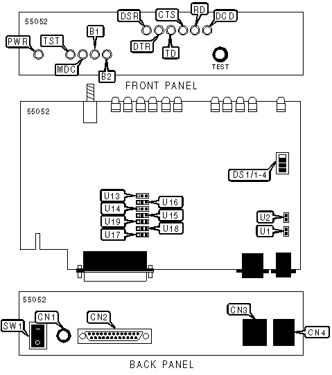
CONNECTIONS | ||||||
|
Function |
Label |
Function |
Label | |||
|
Power |
CN1 |
Line out (RJ-11) |
CN4 | |||
|
25-pin serial port |
CN2 |
Power switch |
SW1 | |||
|
ISDN interface (RJ-45 connector) |
CN3 | |||||
|
USER CONFIGURABLE SETTINGS | ||
|
Setting |
Label |
Position |
|
í Transmission channel in high impedence mode |
U1 |
Open |
|
Transmit termination set to 100Ohm |
U1 |
Closed |
|
í Receive channel in high impedence mode |
U2 |
Open |
|
Receive termination set to 100Ohm |
U2 |
Closed |
|
PORT INTERFACE SELECTION | |||||||
|
Setting |
U13 |
U14 |
U15 |
U16 |
U17 |
U18 |
U19 |
|
í V.24/V.28 interface |
1 & 2 |
1 & 2 |
1 & 2 |
1 & 2 |
1 & 2 |
1 & 2 |
1 & 2 |
|
V.35 interface |
2 & 3 |
2 & 3 |
2 & 3 |
2 & 3 |
2 & 3 |
2 & 3 |
2 & 3 |
|
Note: Pins designated are in the closed position | |||||||
|
POWER ON CONFIGURATION | ||||
|
Setting |
DS1/1 |
DS1/2 |
DS1/3 |
DS1/4 |
|
í Unidentified |
Off |
Off |
Off |
Off |
|
Factory configuration 0 |
Off |
Off |
On |
Off |
|
Factory configuration 1 |
On |
Off |
On |
Off |
|
Factory configuration 2 |
Off |
On |
On |
Off |
|
Factory configuration 3 |
On |
On |
On |
Off |
|
Asynchronous V25bis |
Off |
Off |
Off |
On |
|
Synchronous V25bis |
Off |
Off |
On |
On |
|
DIAGNOSTIC LED(S) | |||
|
LED |
Color |
Status |
Condition |
|
PWR |
Green |
On |
Power is on |
|
PWR |
Green |
Off |
Power is off |
|
TST |
Red |
On |
Unit is conducting a test |
|
TST |
Red |
Blinking |
Error detected during self test |
|
TST |
Red |
Off |
Unit not conducting a test |
|
MDC |
Red |
On |
DTE interface connected to modem/fax |
|
MDC |
Red |
Off |
DTE interface connected to the TA |
|
B1 |
Red |
On |
B1 channel in use |
|
B1 |
Red |
Off |
B1 channel inactive |
|
B1 |
Red |
Blinking |
B1 channel busy |
|
B2 |
Red |
On |
B2 channel in use |
|
B2 |
Red |
Off |
B2 channel inactive |
|
B2 |
Red |
Blinking |
B2 channel busy |
|
DSR |
Red |
On |
Terminal Adapter is ready |
|
DSR |
Red |
Off |
Terminal Adapter not ready |
|
DTR |
Red |
On |
Computer is ready |
|
DTR |
Red |
Off |
Computer is not ready |
|
TD |
Red |
On |
Modem is transmitting data |
|
TD |
Red |
Off |
Modem is not transmitting data |
|
CTS |
Red |
On |
CTS signal is high. TA ready to send data |
|
CTS |
Red |
Off |
CTS signal is low |
|
RD |
Red |
On |
Modem is receiving data |
|
RD |
Red |
Off |
Modem is not receiving data |
|
DCD |
Red |
On |
Data carrier present |
|
DCD |
Red |
Off |
Data carrier not present. Connection not established |
|
SUPPORTED COMMAND SET (DIGITAL) |
|
Basic AT Commands |
|
AT, A/ |
|
E, Q, V, W |
|
&C, &R, &Z |
|
S Registers |
|
S3, S4, S12, S25, S26 |
|
Note: See MHI Help File for full command documentation. |
|
SUPPORTED COMMAND SET (ANALOG) |
|
Basic AT Commands |
|
AT, A/ |
|
A, E, H, L, M, O, Q, V, W, X, Y, Z |
|
&C, &M, &Q, &R, &T, &V, &W, &X, &Y, &Z |
|
Extended AT commands |
|
\A, \B, \G, \K, \N |
|
%C, %E, %L |
|
S Registers |
|
S0, S1, S2, S3, S4, S5, S6 ,S7, S8, S9, S10, S12, S18, S25, S26, S30, S32, S33, S95 |
|
Special commands |
|
+MS, )M |
|
V.25bis commands |
|
CIC, CRN, CRS, DIC, PRN |
|
Note: See MHI Help File for full command documentation. |
|
DIGITAL OR ANALOG MODEM SELECTION | |
|
Type: |
Configuration |
|
Format: |
AT [cmds] $Mn [cmds] |
|
Description: |
Selects digital or analog for preliminary setup |
|
Note: |
If the call is being made using the digital section, the remote user is ISDN. If the call is being made using the analog section, the remote user is PSTN |
|
Command |
Function |
|
$M0 |
Computer serial interface is connected to the digital modem section |
|
$M1 |
Computer serial interface is connected to the analog modem section |
PROPRIETARY AT COMMAND SET (DIGITAL)
|
AUTO-MODE DETECTION | ||
|
Type: |
Configuration | |
|
Format: |
AT [cmds] Nn [cmds] | |
|
Description: |
Selects various options for the automatic detection and negotiation of protocols during the handshake process if the modem is communicating with a remote modem of dissimilar speed. | |
|
Command |
Asynchronous Mode |
Synchronous Mode |
|
N0 |
If the DTE interface is equal or more than 38.4Kbps and S37=255, the connection is active at 38.4Kbps. Otherwise, connection is established at speed selected by S37. |
If the DTE interface is equal or more than 115.2Kbps and S37=255, the connection is active at 64Kbps in transparent mode. Otherwise, connection is established at speed selected by S37. |
|
í N1 |
Line connection speed starts at 19.2Kbps and follows DTE interface. |
Line connection speed starts at 48Kbps V.110 and follows DTE interface. |
|
COMMUNICATIONS MODE | |
|
Type: |
Configuration |
|
Format: |
AT [cmds] &Mn [cmds] |
|
Description: |
Selects communications mode options |
|
Command |
Mode |
|
&M0 |
Buffered asynchronous mode |
|
&M1 |
Asynchronous off-line command mode and synchronous connect mode. |
|
&M2 |
Asynchronous off-line command mode. Modem autodials first number in directory, then synchronous connect mode. |
|
&M4 |
Direct mode (V.110) |
|
COMMUNICATIONS MODE | |
|
Type: |
Configuration |
|
Format: |
AT [cmds] &Qn [cmds] |
|
Description: |
Selects communications mode options |
|
Command |
Mode |
|
&Q0 |
Buffered asynchronous mode |
|
&Q1 |
Asynchronous off-line command mode and synchronous connect mode |
|
&Q2 |
Asynchronous off-line command mode, Modem autodials first number in directory, then synchronous connect mode. |
|
&Q4 |
Direct mode (V.110) |
|
CONFIGURATION PROFILES | |
|
Type: |
Immediate |
|
Format: |
AT [cmds] &V [cmds] |
|
Description: |
Displays active and stored configuration profiles |
|
Command |
Function |
|
&V0 |
Displays the active profile, the 0 and 1 st user configuration and the first four stored numbers |
|
&V1 |
Displays the 2 nd and 3rd user configuration |
|
&V2 |
Displays every stored phone number |
|
&V3 |
Displays the supplementary services profile |
|
DATA COMPRESSION | |
|
Type: |
Immediate |
|
Format: |
AT [cmds] &Un |
|
Description: |
Selects data compression |
|
Command |
Function |
|
í &U0 |
Data compression disabled |
|
&U1 |
Error corrected data compression enabled (V.120) |
|
DATA SET READY (DSR) | |
|
Type: |
Configuration |
|
Format: |
AT [cmds] &Sn [cmds] |
|
Description: |
Selects DSR options |
|
Command |
Function |
|
í &S0 |
DSR forced high |
|
&S1 |
DSR high only while modem is handshaking or connected |
|
DATA TERMINAL READY (DTR) | |
|
Type: |
Configuration |
|
Format: |
AT [cmds] &Dn [cmds] |
|
Description: |
Selects modem response to DTR |
|
Command |
Function |
|
í &D0 |
DTR override |
|
&D1 |
DTR toggle causes online command mode |
|
&D2 |
Normal DTR operations |
|
&D3 |
Resets on receipt of DTR |
|
DIAL | |
|
Type: |
Immediate |
|
Format: |
AT [cmds] D<#> [cmds] |
|
Description: |
Dials telephone number according to any modifiers included in the string |
|
Note: |
Any combination of modifiers can be used to produce the desired dial functions in sequence. |
|
Command |
Function |
|
DS=n |
Dial stored telephone number n (0-19) |
|
DT |
Call is switched to digital interface |
|
DP |
Call is switched to analog interface |
|
FACTORY DEFAULT PROFILE | |
|
Type: |
Configuration |
|
Format: |
AT [cmds] &F [cmds] |
|
Description: |
Sets values in active profile to values found in the default profile |
|
Command |
Function |
|
&F0 |
Load active profile the factory profile 0 |
|
&F1 |
Load active profile the factory profile 1 |
|
&F2 |
Load active profile the factory profile 2 |
|
&F3 |
Load active profile the factory profile 3 |
|
FLOW CONTROL | |
|
Type: |
Configuration |
|
Format: |
AT [cmds] &Kn [cmds] |
|
Description: |
Enables flow control options |
|
Command |
Function |
|
&K0 |
Flow control disabled |
|
&K3 |
RTS/CTS flow control enabled |
|
&K4 |
XON/XOFF flow control enabled. Modem does not transmit XON/XOFF characters received from computer to remote |
|
&K8 |
Unidirectional XON/XOFF flow control enabled |
|
&K12 |
XON/XOFF flow control enabled. Modem transmits XON/XOFF characters received from computer to remote |
|
&K16 |
V.110 XON/XOFF flow control enabled. Flow control between local and remote modems only. Flow control between modem and computer is disabled. |
|
&K20 |
V.110 XON/XOFF flow control enabled. |
|
HOOK CONTROL | |
|
Type: |
Immediate |
|
Format: |
AT [cmds] Hn [cmds] |
|
Description: |
Selects whether the device is on-hook or off-hook |
|
Command |
Function |
|
H0 |
TA commanded to go on-hook (hang-up) |
|
ON-LINE | |
|
Type: |
Immediate |
|
Format: |
AT [cmds] On [cmds] |
|
Description: |
Controls on-line command (data transmission) state options. |
|
Command |
Function |
|
O0 |
On-line command mode with no retraining enabled |
|
REPORT INFORMATION | |
|
Type: |
Immediate |
|
Format: |
AT [cmds] In [cmds] |
|
Description: |
Displays information requested |
|
Command |
Function |
|
I0 |
Reports model |
|
I1 |
Reports ROM checksum |
|
I2 |
Tests and reports ROM checksum |
|
I3 |
Reports revision level |
|
I4 |
Display central office |
|
RESTORE PROFILE ON POWER-UP | |
|
Type: |
Configuration |
|
Format: |
AT [cmds] &Yn [cmds] |
|
Description: |
Restores a selected profile into the active profile on power-up (hard reset) |
|
Command |
Function |
|
&Y0 |
Restore profile 0 on power-up |
|
&Y1 |
Restore profile 1 on power-up |
|
&Y2 |
Restore profile 2 on power-up |
|
&Y3 |
Restore profile 3 on power-up |
|
SELECT CALL PROGRESS RESULT CODES | |
|
Type: |
Configuration |
|
Format: |
AT [cmds] Xn [cmds] |
|
Description: |
Enables selection of tone detection and associated result code format options |
|
Command |
Function |
|
X0 |
Result codes 0 - 4 enabled. |
|
X1 |
Extended result codes enabled. |
|
SOFT RESET | |
|
Type: |
Immediate |
|
Format: |
AT [cmds] Zn [cmds] |
|
Description: |
Restores modem profiles previously saved in non-volatile RAM using the &W command. |
|
Command |
Function |
|
Z0 |
Restore setting 0 |
|
Z1 |
Restore setting 1 |
|
Z2 |
Restore setting 2 |
|
Z3 |
Restore setting 3 |
|
STORE ACTIVE PROFILE | |
|
Type: |
Configuration |
|
Format: |
AT [cmds] &Wn [cmds] |
|
Description: |
Writes the values for the active profile into the non-volatile RAM |
|
Command |
Function |
|
&W0 |
Write the active profile to stored profile 0 |
|
&W1 |
Write the active profile to stored profile 1 |
|
&W2 |
Write the active profile to stored profile 2 |
|
&W3 |
Write the active profile to stored profile 3 |
|
TEST MODES | |
|
Type: |
Immediate |
|
Format: |
AT [cmds] &Tn |
|
Description: |
Selects test options |
|
Command |
Function |
|
&T0 |
End current test |
|
&T1 |
Begin local analog loopback test |
|
&T3 |
Begin B1 channel local digital loopback |
EXTENDED AT COMMAND SET (DIGITAL)
|
B-CHANNEL PROTOCOL | |
|
Type: |
Configuration |
|
Format: |
AT [cmds] %A2=n [cmds] |
|
Description: |
Determines rate adaptation protocol on B-channel |
|
Command |
Function |
|
í %A2=1 |
V.110 |
|
%A2=2 |
V.120 |
|
B-CHANNEL SELECTION | |
|
Type: |
Configuration |
|
Format: |
AT [cmds] %A3=n [cmds] |
|
Description: |
Selects data channel |
|
Command |
Function |
|
í %A3=2 |
B1 channel selected. If busy select B2 channel |
|
%A3=3 |
B1 channel selected. If busy initiate hang-up |
|
%A3=4 |
B2 channel selected. If busy select B1 channel |
|
%A3=5 |
B2 channel selected. If busy initiate hang-up |
|
COMMAND SET | |
|
Type: |
Configuration |
|
Format: |
AT [cmds] %Vn [cmds] |
|
Description: |
Defines the AT or V.25bis command set |
|
Command |
Function |
|
%V0 |
AT command set |
|
%V1 |
Asynchronous V.25bis command set |
|
%V3 |
Synchronous V.25bis HDLC command set |
|
COMPRESSION | |
|
Type: |
Configuration |
|
Format: |
AT [cmds] %Cn [cmds] |
|
Description: |
Selects data compression |
|
Command |
Function |
|
%C0 |
Data compression disabled |
|
%C1 |
MNP5 enabled |
|
FLASH EPROM CODE UPGRADE | |
|
Type: |
Configuration |
|
Format: |
AT [cmds] %Fn [cmds] |
|
Description: |
Initiates Flash EPROM code upgrade |
|
RESET | |
|
Type: |
Configuration |
|
Format: |
AT [cmds] %Z1 [cmds] |
|
Description: |
Master reset and load the configuration specified by the &Y command |
SPECIAL COMMANDS (DIGITAL)
|
AUDIO/SPEECH ISDN CALL | |
|
Type: |
Configuration |
|
Format: |
AT [cmds] *Bn [cmds] |
|
Description: |
Selects type of ISDN analog call |
|
Command |
Function |
|
í *B0 |
Speech mode enabled |
|
*B1 |
3.1KHz audio enabled |
|
CALLER ID | |
|
Type: |
Configuration |
|
Format: |
AT [cmds] *In [cmds] |
|
Description: |
Enables/disables originate call identification function |
|
Command |
Function |
|
*I0 |
Caller ID disabled |
|
*I1 |
Caller ID enabled |
|
MULTISUBSCRIBER NUMBER | |
|
Type: |
Configuration |
|
Format: |
AT [cmds] *Mn [cmds] |
|
Description: |
Permits the association of a maximum of 8 consecutive numbers to a BRI access of the national plan number |
|
Command |
Function |
|
í *M0 |
MSN disabled |
|
*M1 |
MSN enabled |
|
PROGRAMMING PROMPT | |
|
Type: |
Configuration |
|
Format: |
AT [cmds] $Pn [cmds] |
|
Description: |
Enables/disables programming prompt |
|
Command |
Function |
|
í $P0 |
Interface prompt disabled |
|
$P1 |
Interface prompt enabled |
|
SUBADDRESS | |
|
Type: |
Configuration |
|
Format: |
AT [cmds] *Sn [cmds] |
|
Description: |
Identifies address of called modem |
|
Command |
Function |
|
í *S0 |
Subaddress function disabled |
|
*S1 |
Subaddress function enabled |
|
STORE CALLER ID NUMBER | |
|
Type: |
Configuration |
|
Format: |
AT [cmds] !N1=n [cmds] |
|
Description: |
Stores telephone number n for the caller ID function. !N1=? displays the stored telephone number. |
|
STORE MULTISUBSCRIBER NUMBER | |
|
Type: |
Configuration |
|
Format: |
AT [cmds] !N2=n [cmds] |
|
Description: |
Stores own telephone number n for the MSN. !N2=? displays the stored multisubscriber number. |
|
STORE SUBADDRESS NUMBER | |
|
Type: |
Configuration |
|
Format: |
AT [cmds] !N3=n [cmds] |
|
Description: |
Stores subaddress field with a maximum of four numbers. !N3=? displays the stored subaddress field. |
S(status) REGISTERS (DIGITAL)
|
AUTO ANSWER RING COUNT | |
|
Type: |
Register |
|
Format |
AT [cmds] S0=n [cmds] |
|
Range: |
1-5 |
|
Unit: |
1 ring |
|
Description: |
Sets the number of rings allowed before the modem automatically goes off-hook |
Note: If S0=0, automatic-answering is disabled. The A command must be used to go off-hook. | |
|
BACKSPACE CHARACTER | |
|
Type: |
Register |
|
Format |
AT [cmds] S5=n [cmds] |
|
Range: |
0-127 |
|
Unit: |
ASCII |
|
Description: |
Selects a character used for backspace <BS> |
|
BIT-MAPPED REGISTER S31 | ||||
|
Type: |
Register | |||
|
Format: |
AT [cmds] S31=n [cmds] | |||
|
Range: |
0-255 | |||
|
Description: |
Selects V.25bis command mode | |||
|
Bit |
Value |
Function | ||
|
1,0 |
í 0 |
V.25bis asynchronous mode | ||
|
3, 2 |
í 01 |
V.25bis disabled V.25bis enabled | ||
|
CALL WAITING TIME | |
|
Type: |
Register |
|
Format |
AT [cmds] S13=n [cmds] |
|
Range: |
0-255 |
|
Unit: |
1sec |
|
Description: |
Selects the duration that the buzzer/Test led flashes when a new call is detected. A value of 0 disables call waiting time. |
|
DCE LINE SPEED | |
|
Type: |
Register |
|
Format |
AT [cmds] S37=n [cmds] |
|
Description: |
Sets the maximum allowable data exchange rate attempted during handshake process. |
|
Command |
Function |
|
S37=0, 255 |
Speed of last connection |
|
S37=4 |
600bps |
|
S37=5 |
1200bps |
|
S37=6 |
2400bps |
|
S37=15 |
4800bps |
|
S37=16 |
7200bps |
|
S37=17 |
9600bps |
|
S37=18 |
12.0Kbps |
|
S37=19 |
14.4Kbps |
|
S37=27 |
19.2Kbps |
|
S37=50 |
38.4Kbps |
|
S37=51 |
48.0Kbps |
|
S37=53 |
64.OKbps |
|
ESCAPE CHARACTER | |
|
Type: |
Register |
|
Format |
AT [cmds] S2=n [cmds] |
|
Range: |
0-127 |
|
Unit: |
ASCII |
|
Description: |
Selects a character used for the escape sequence |
Note: A value greater than 127 will disable the escape sequence. | |
|
FLOW CONTROL | ||
|
Type: |
Register | |
|
Format: |
AT [cmds] S49=n [cmds] | |
|
Description: |
Displays the value of the &K command, which specifies the DTE flow control setting | |
|
Command |
Function | |
|
S49=0 |
No DTE flow control | |
|
S49=3 |
RTS/CTS flow control enabled | |
|
S49=4 |
Bi-directional XON/XOFF flow control enabled | |
|
S49=5 |
Transparent bi-directional XON/XOFF flow control enabled | |
|
NO CARRIER TIME-OUT | |
|
Type: |
Register |
|
Format |
AT [cmds] S7=n [cmds] |
|
Range: |
1-255 |
|
Unit: |
1 second |
|
Description: |
Maximum wait time the modem uses after dialing to detect a carrier signal from the remote modem for both originating and answering calls. |
|
POINTER FOR CALL-BACK AND AUTOLOGON | |
|
Type: |
Register |
|
Format |
AT [cmds] S34=n [cmds] |
|
Range: |
0-20, 255 |
|
Unit: |
Unidentified |
|
Description: |
Establishes the memory location accessed to initiate autologon or callback procedures. 20 will cause the phonebook to scroll. 255 disables function |
|
RING COUNT | |
|
Type: |
Register |
|
Format |
AT [cmds] S1= n [cmds] |
|
Range: |
1-5 |
|
Unit: |
1 ring |
|
Description: |
Counts the number of ring-cycles the modem receives |
Note: S1 is reset to 0 if no ring is detected within an eight-second window. | |
PROPRIETARY AT COMMAND SET (ANALOG)
|
COMMUNICATION PROTOCOLS | |
|
Type: |
Configuration |
|
Format: |
AT [cmds] Bn [cmds] |
|
Description: |
Selects the communication protocol for data calls |
Note: The B command allows the simultaneous selection of more than one suffix, enabling multiple protocols. | |
|
Command |
Protocol |
|
B0 |
ITU-T V.22 at 300 or 1200bps |
|
DATA SET READY (DSR) | |
|
Type: |
Configuration |
|
Format: |
AT [cmds] &Sn [cmds] |
|
Description: |
Selects DSR options |
|
Command |
Function |
|
í &S0 |
DSR forced high |
|
&S1 |
DSR high only while modem is handshaking or connected |
|
DATA TERMINAL READY (DTR) | |
|
Type: |
Configuration |
|
Format: |
AT [cmds] &Dn [cmds] |
|
Description: |
Selects modem response to DTR |
|
Command |
Function |
|
&D0 |
DTR override |
|
&D1 |
DTR toggle causes online command mode |
|
í &D2 |
Normal DTR operations |
|
&D3 |
Resets on receipt of DTR |
|
DIAL | |
|
Type: |
Immediate |
|
Format: |
AT [cmds] D<#> [cmds] |
|
Description: |
Dials telephone number according to any modifiers included in the string |
|
Note: |
Any combination of modifiers can be used to produce the desired dial functions in sequence. |
|
Command |
Function |
|
DL |
Re-dial last number |
|
DP |
Dial using analog modem section |
|
DS=n |
Dial stored telephone number n (0-3) |
|
DT |
Dial using digital modem section |
|
DW |
Dialing resumed following dial tone detection |
|
D, |
Dialing paused for amount of time specified in S8 register |
|
D@ |
Wait for Quite Answer function enabled. Modem waits until a "quiet answer," a ring-back signal followed by five seconds of silence. |
|
D! |
Flash function initiated. Modem commanded to go off-hook for specified time before returning on-hook. |
|
D; |
Modem returned to idle state after dialing. The semicolon can only be placed at the end of the dial command. |
|
FACTORY DEFAULT PROFILE | |
|
Type: |
Configuration |
|
Format: |
AT [cmds] &F [cmds] |
|
Description: |
Sets values in active profile to values found in the default profile |
|
Command |
Function |
|
&F0 |
Factory default profile 0 |
|
&F1 |
Factory default profile 1 |
|
FLOW CONTROL | |
|
Type: |
Configuration |
|
Format: |
AT [cmds] &Kn [cmds] |
|
Description: |
Enables flow control options |
|
Command |
Function |
|
&K0 |
Flow control disabled |
|
í &K3 |
RTS/CTS flow control enabled |
|
&K4 |
XON/XOFF flow control enabled |
|
&K5 |
Transparent XON/XOFF flow control enabled |
|
&K6 |
RTS/CTS and XON/XOFF flow control enabled |
|
GUARD TONE | |
|
Type: |
Configuration |
|
Format: |
AT [cmds] &Gn [cmds] |
|
Description: |
Commands the modem to transmit a guard tone in V.22/V.22bis |
|
Command |
Function |
|
&G0 |
Guard tone disabled |
|
&G2 |
Guard tone enabled |
|
LINE MODULATION | |
|
Type: |
Configuration |
|
Format: |
AT [cmds] Fn [cmds] |
|
Description: |
Command supported only for compatibility. No function is performed |
|
REPORT INFORMATION | |
|
Type: |
Immediate |
|
Format: |
AT [cmds] In [cmds] |
|
Description: |
Displays information requested |
|
Command |
Function |
|
I0 |
Reports maximum line speed |
|
I1 |
Reports product type |
|
I2 |
Reports checksum firmware |
|
I3 |
Reports product name |
|
I4 |
Reports firmware release |
|
I5 |
Reports active Country Code |
EXTENDED AT COMMANDS (ANALOG)
|
ABORT KEY CONTROL | |
|
Type: |
Configuration |
|
Format: |
AT [cmds] %Kn [cmds] |
|
Description: |
Enable/disable abort key during dialing |
|
Command |
Function |
|
%K0 |
Abort key during dialing enabled |
|
%K1 |
abort key during dialing disabled |
|
DSR WINK | |
|
Type: |
Immediate |
|
Format: |
AT [cmds] %S [cmds] |
|
Description: |
Returns a value which indicates line signal quality |
|
Command |
Function |
|
%S0 |
Data set ready in accordance with &S |
|
%S1 |
When DTR is forced high, and the modem is goes off-hook, DTR is off for 1sec. |
|
LINE SIGNAL QUALITY | |
|
Type: |
Immediate |
|
Format: |
AT [cmds] %Q [cmds] |
|
Range: |
000-127 |
|
Unit: |
Unidentified |
|
Description: |
Returns a value which indicates line signal quality. Values 000-007 indicate good line quality. Values 008-127 indicate poor line quality, disturbed signal |
|
MAKE BUSY | |
|
Type: |
Configuration |
|
Format: |
AT [cmds] %Bn [cmds] |
|
Description: |
Make busy (off-hook) if DTR lost |
|
Command |
Function |
|
í %B0 |
Make busy disabled |
|
%B1 |
Make busy enabled if S25=0. When DTR is low, the modem goes off-hook |
SPECIAL COMMANDS (ANALOG)
|
MNP10 - LINK NEGOTIATION | |
|
Type: |
Configuration |
|
Format: |
AT [cmds] *Hn [cmds] |
|
Description: |
Sets the speed at which MNP10 link negotiation will occur |
|
Command |
Function |
|
*H0 |
Link will be negotiated at highest possible speed |
|
*H1 |
Link will be negotiated at 1200bps |
|
MNP - EXTENDED SERVICES | |
|
Type: |
Configuration |
|
Format: |
AT [cmds] -Kn [cmds] |
|
Description: |
Selects MNP extended services |
|
Command |
Function |
|
-K0 |
MNP extended services disabled |
|
-K1 |
MNP extended services enabled if modem was previously in V.42bis mode |
V.25bis COMMANDS (ANALOG)
|
LOCAL CONFIGURATION | |
|
Type: |
Immediate |
|
Format: |
CNLn |
|
Description: |
Any AT command may be entered as a parameter of this command |
|
REQUEST LIST OF STORED NUMBERS | |
|
Type: |
Immediate |
|
Format: |
RLN |
|
Description: |
Requests the list of phone numbers stored in memory |
S(status) REGISTERS (ANALOG)
|
TRANSMISSION LEVEL - FAX | |
|
Type: |
Register |
|
Format: |
AT [cmds] S92=n [cmds] |
|
Range: |
3-15 |
|
Unit: |
-1 dBm |
|
Description: |
Sets the signal level for transmission while in fax mode |
|
TRANSMISSION LEVEL - LEASED-LINE | |
|
Type |
Register or Configuration |
|
Format |
AT [cmds] S91=n [cmds] |
|
Range |
3-15 |
|
Unit |
-1 dBm |
|
Description |
Sets the signal level for transmission over leased-lines |