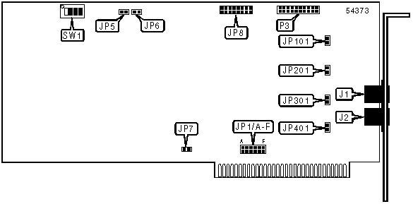
DIALOGIC CORPORATION
D/41D (REV. 3)
|
Card Type |
Telephony |
|
I/O Options |
AEB bus, Line in via RJ-14 (2) |
|
Data Bus |
8-bit ISA |
|
Line Type |
Loop-start |
|
CONNECTIONS | |||
|
Function |
Label |
Function |
Label |
|
Line in via RJ-14 connector |
J1 |
Analog expansion bus |
P3 |
|
Line in via RJ-14 connector |
J2 | ||
|
USER CONFIGURABLE SETTINGS | |||
|
Setting |
Label |
Position | |
| » |
IRQ termination enabled |
JP7 |
Open |
|
IRQ termination disabled |
JP7 |
Closed | |
| » |
Board will use internal loop-start interface for input |
JP8 |
Closed |
|
Board will use T1 interface via AEB bus for input |
JP8 |
Open | |
| » |
Disabled board will not answer incoming calls |
SW1/4 |
Off |
|
Disabled board will send busy signal to incoming calls |
SW1/4 |
On | |
|
Note:If multiple D/4x cards are installed in a system, JP7 should be closed for only one of them. | |||
|
CHANNEL 1 RING DETECTION | |
|
Setting |
JP101 |
|
Ring detection threshold normal |
Open |
|
Ring detection threshold lowered |
Closed |
|
Note: A lowered threshold may cause false detection of rings | |
|
CHANNEL 2 RING DETECTION | |
|
Setting |
JP201 |
|
Ring detection threshold normal |
Open |
|
Ring detection threshold lowered |
Closed |
|
Note: A lowered threshold may cause false detection of rings | |
|
CHANNEL 3 RING DETECTION | |
|
Setting |
JP301 |
|
Ring detection threshold normal |
Open |
|
Ring detection threshold lowered |
Closed |
|
Note: A lowered threshold may cause false detection of rings | |
|
CHANNEL 4 RING DETECTION | |
|
Setting |
JP401 |
|
Ring detection threshold normal |
Open |
|
Ring detection threshold lowered |
Closed |
|
Note: A lowered threshold may cause false detection of rings | |
|
BASE I/O ADDRESS | ||||||
|
Setting |
JP5 |
JP6 |
SW1/1 |
SW1/2 |
SW1/3 | |
|
A0000h |
Closed |
Open |
Off |
Off |
Off | |
|
A2000h |
Closed |
Open |
Off |
Off |
On | |
|
A4000h |
Closed |
Open |
Off |
On |
Off | |
|
A6000h |
Closed |
Open |
Off |
On |
On | |
|
A8000h |
Closed |
Open |
On |
Off |
Off | |
| » |
D0000h |
Open |
Open |
Off |
Off |
Off |
|
D6000h |
Open |
Open |
Off |
On |
On | |
|
D8000h |
Open |
Open |
On |
Off |
Off | |
|
DA000h |
Open |
Open |
On |
Off |
On | |
|
DC000h |
Open |
Open |
On |
On |
Off | |
|
DE000h |
Open |
Open |
On |
On |
On | |
|
Note: A total of 32 base address settings are available. The switches are a binary representation of the decimal memory addresses. JP5 is the Most Significant Bit and switch SW1/3 is the Least Significant Bit. The switches have the following decimal values: JP5=131072 JP6=65536, SW1/1=32768, SW1/2=16384, SW1/3=8192. Turn off the switches and add the values of the switches to obtain the correct memory address. (Off=1, On=0) | ||||||
|
INTERRUPT | |||||||
|
Setting |
JP1/A |
JP1/B |
JP1/C |
JP1/D |
JP1/E |
JP1/F | |
| » |
|
Closed |
Open |
Open |
Open |
Open |
Open |
|
IRQ3 |
Open |
Closed |
Open |
Open |
Open |
Open | |
|
IRQ4 |
Open |
Open |
Closed |
Open |
Open |
Open | |
|
IRQ5 |
Open |
Open |
Open |
Closed |
Open |
Open | |
|
IRQ6 |
Open |
Open |
Open |
Open |
Closed |
Open | |
|
IRQ7 |
Open |
Open |
Open |
Open |
Open |
Closed | |
|
Note: All D/21D & D/41D boards in the system should be set to the same interrupt. | |||||||