MADGE NETWORKS, LTD.
SMART 16/4 AT RINGNODE
|
NIC Type |
Token-Ring |
|
Transfer Rate |
4/16Mbps |
|
Data Bus |
16-bit ISA |
|
Topology |
Ring |
|
Wiring Type |
Shielded twisted pair Unshielded twisted pair |
|
Boot ROM |
Available |
|
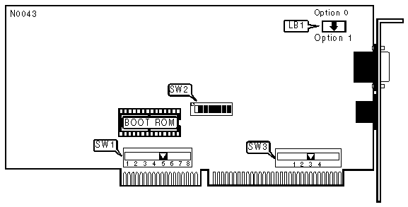
BASE I/O AND BOOT ROM ADDRESS | ||||
|
Address |
Boot ROM Address |
SW2/1 |
SW2/2 | |
| » |
0A20-0A2Fh |
CC000-CDFFFh |
On |
On |
|
1A20-1A2Fh |
DC000-DDFFFh |
Off |
On | |
|
2A20-2A2Fh |
CE000-CFFFFh |
On |
Off | |
|
3A20-3A2Fh |
DE000-DFFFFh |
Off |
Off | |
|
INTERRUPT REQUEST | ||
|
IRQ |
SW1 | |
| » |
3 |
Position 7 |
|
2/9 |
Position 8 | |
|
5 |
Position 6 | |
|
7 |
Position 5 | |
|
10 |
Position 4 | |
|
11 |
Position 3 | |
|
12 |
Position 2 | |
|
15 |
Position 1 | |
|
Note:This switch pack utilizes a single 8 position switch. | ||
|
BOOT ROM | ||
|
Setting |
SW2/3 | |
| » |
Disabled |
Off |
|
Enabled |
On | |
|
DMA CHANNEL ENABLE | ||
|
Setting |
SW2/4 | |
| » |
Enabled |
On |
|
Disabled |
Off | |
|
Note:This switch has no effect on the NIC if it is installed in an 8-bit slot. | ||
|
8/16-BIT MODE | ||
|
Setting |
SW2/5 | |
| » |
8/16-bit mode |
On |
|
Forced 8-bit mode |
Off | |
|
Note:If an 8-bit transfer mode is required and the NIC is installed in a 16-bit slot, use forced 8-bit mode. If the NIC is to be used in a Novell Netware 386 file server, 8/16-bit mode must be used. | ||
|
COMPATIBILITY MODE | ||
|
Setting |
SW2/6 | |
| » |
Normal ISA bus timing |
On |
|
Alternate ISA bus timing |
Off | |
|
Note:Alternate ISA bus timing is used if the host computer is not 100% ISA bus compatible (such as the IBM PS/2 model 30-286) or if the Madge Ringnode diagnostics program fails to locate the NIC. | ||
|
DMA CHANNEL BUS | |||
|
Setting |
SW2/7 | ||
| » |
Asynchronous bus (uses host system's clock) |
On | |
|
Synchronous bus (uses NIC on-board clock) |
Off | ||
|
Note :The synchronous bus speed is used for systems that have a clock speed less than 10MHz. | |||
|
NETWORK SPEED | ||
|
Setting |
SW2/8 | |
| » |
4Mbps |
On |
|
16Mbps |
Off | |
|
Note:All NIC cards on the network must be set to the same speed for proper operation. | ||
|
DMA CHANNEL | |
|
Channel |
SW3 |
|
1 |
Position 1 |
|
3 |
Position 2 |
|
5 |
Position 3 |
|
6 |
Position 4 |
|
Note:This switch pack utilizes a single 8 position switch. | |
|
CABLE TYPE | |
|
Type |
LB1 Orientation |
|
Shielded twisted pair (DB-9 connector) |
Option 1 |
|
Shielded/Unshielded twisted pair (RJ-45 jack) |
Option 0 |
|
Note:Ensure that the header block completely covers all pins on the base. | |