IMC NETWORK CORPORATION
ETHERNIC/2000 COMBO
|
NIC Type |
Ethernet |
|
Transfer Rate |
10Mbps |
|
Data Bus |
8/16-bit ISA |
|
Topology |
Linear Bus |
|
Wiring Type |
RG--58A/U 50ohm coaxial RG--62A/U 93ohm coaxial 75ohm coaxial Shielded/Unshielded twisted pair AUI transceiver via DB-15 port |
|
Boot ROM |
Available |
|
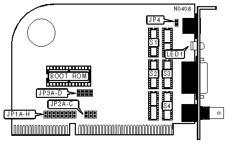
INTERRUPT REQUEST | |||||||||
|
IRQ |
JP1A |
JP1B |
JP1C |
JP1D |
JP1E |
JP1F |
JP1G |
JP1H | |
|
2/9 |
Open |
Open |
Open |
Closed |
Open |
Open |
Open |
Open | |
| » |
3 |
Closed |
Open |
Open |
Open |
Open |
Open |
Open |
Open |
|
4 |
Open |
Closed |
Open |
Open |
Open |
Open |
Open |
Open | |
|
5 |
Open |
Open |
Closed |
Open |
Open |
Open |
Open |
Open | |
|
10 |
Open |
Open |
Open |
Open |
Closed |
Open |
Open |
Open | |
|
11 |
Open |
Open |
Open |
Open |
Open |
Closed |
Open |
Open | |
|
12 |
Open |
Open |
Open |
Open |
Open |
Open |
Closed |
Open | |
|
15 |
Open |
Open |
Open |
Open |
Open |
Open |
Open |
Closed | |
|
Note:If a Boot ROM is installed, see the I/O base address & Boot ROM address table for valid interrupt settings. | |||||||||
|
COMPATIBILITY MODE | |||
|
Setting |
JP2A |
JP2B | |
| » |
Disabled |
Closed |
Open |
|
Enabled |
Open |
Closed | |
|
Note:On some systems the data bus timing is not truly IBM PC/AT compatible. If the card is not initializing enabling compatibility mode may allow the card to operate properly.
| |||
|
DATA BUS SIZE | ||
|
Setting |
JP2C | |
| » |
Autosense |
Closed |
|
8-bit |
Open | |
|
Note:In autosense mode the card automatically detects if it is in a 16-bit or 8-bit slot. On some Rev. 01 cards this jumper is incorrectly labeled TURBO. | ||
|
I/O BASE ADDRESS & BOOT ROM ADDRESS | |||||
|
I/O Address |
Boot ROM Address |
JP3A |
JP3B |
JP3C | |
|
200 |
N/A |
Open |
Open |
Open | |
|
220 |
N/A |
Closed |
Open |
Open | |
|
240 |
N/A |
Open |
Closed |
Open | |
|
260 |
N/A |
Closed |
Closed |
Open | |
| » |
300 |
C8000h (IRQ3) |
Open |
Open |
Closed |
|
320 |
CC000h (IRQ5) |
Closed |
Open |
Closed | |
|
340h |
D0000h (IRQ4) |
Open |
Closed |
Closed | |
|
360h |
N/A |
Closed |
Closed |
Closed | |
|
Note:If a boot ROM is to be installed one of the I/O address configurations with a boot ROM address must be used and the indicated IRQ must be set.
| |||||
|
BOOT ROM | ||
|
Setting |
JP3D | |
| » |
Disabled |
Closed |
|
Enabled |
Open | |
|
CABLE TYPE | |||||
|
Type |
S1 |
S2 |
S3 |
S4 | |
| » |
RG--58A/U 50ohm coaxial |
Open |
Installed |
Open |
50ohm (P/N 90-39050) |
|
RG--62A/U 93ohm coaxial |
Open |
Installed |
Open |
93ohm (P/N 90-39093) | |
|
75ohm coaxial |
Open |
Installed |
Open |
75ohm (P/N 90-39075) | |
|
AUI transceiver via DB-15 port |
Open |
Open |
Installed |
N/A | |
|
Shielded/Unshielded twisted pair |
Installed |
Open |
Open |
N/A | |
|
Note:S1, S2, and S3 are sockets for a transformer chip while S4 is a socket for a Cabling Option Resistor Kit (CORK). To choose a cable type insert the appropriate chips into the appropriate sockets. All cards on the
network segment must use the same type of coaxial cable.
| |||||
|
LINK INTEGRITY TEST | ||
|
Setting |
JP3 | |
| » |
Enabled |
Pins 1 & 2 closed |
|
Disabled |
Pins 2 & 3 closed | |
|
Note:The link integrity test is valid only when the cable type is shielded/unshielded twisted pair. | ||
|
DIAGNOSTIC LED(S) | |||
|
LED |
Color |
Status |
Condition |
|
LED1 |
Green |
On |
Twisted pair network connection is good |
|
LED1 |
Green |
Off |
Twisted pair network connection is broken |
|
Note:LED1 indications are only valid when cable type is shielded/unshielded twisted pair. | |||