NEC TECHNOLOGIES, INC.
APC IV SERIES (G9YAN)
|
Processor |
80286 (exact location unidentified) |
|
Processor Speed |
6/8MHz |
|
Chip Set |
Unidentified |
|
Maximum Onboard Memory |
10MB (on external memory cards) |
|
Cache |
None |
|
BIOS |
Unidentified |
|
Dimensions |
355mm x 305mm |
|
I/O Options |
Floppy drive interface, parallel port, serial ports (2) |
|
NPU Options |
80287 (exact location unidentified) |
|
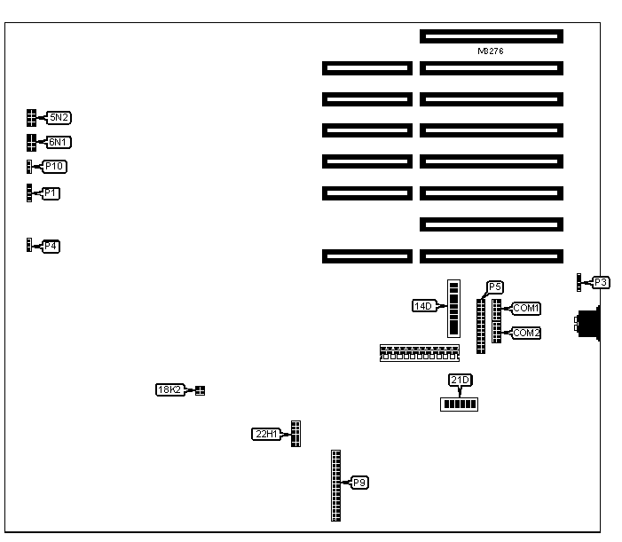
CONNECTIONS | |||
|
Function |
Label |
Function |
Label |
|
Serial port 1 |
COM1 |
Indicator panel |
P4 |
|
Serial port 2 |
COM2 |
Parallel port |
P5 |
|
Speaker |
P1 |
Floppy drive interface |
P9 |
|
External battery |
P3 |
Indicator panel |
P10 |
|
USER CONFIGURABLE SETTINGS | |||
|
Setting |
Label |
Position | |
|
» |
ROM area reserved on I/O channel |
5N2 |
Pins 3 & 6, 4 & 5 closed |
|
APC IV ROM at location 4K, 4M enabled |
5N2 |
Pins 1 & 8, 2 & 7 closed | |
|
» |
BIOS type select 27256 |
6N1 |
Pins 3 & 6, 4 & 5 closed |
|
BIOS type select 27128 |
6N1 |
Pins 1 & 8, 2 & 7 closed | |
|
» |
Factory configured - do not alter |
14D/3 |
Off |
|
» |
Parallel port enabled |
14D/4 |
On |
|
Parallel port disabled |
14D/4 |
Off | |
|
» |
Serial port channel 1 enabled |
14D/5 |
On |
|
Serial port channel 1 disabled |
14D/5 |
Off | |
|
» |
Serial port channel 2 enabled |
14D/6 |
On |
|
Serial port channel 2 disabled |
14D/6 |
Off | |
|
» |
Channel 1 = COM1/channel 2 = COM2 |
14D/7 |
On |
|
Channel 1 = COM2/channel 2 = COM1 |
14D/7 |
Off | |
|
» |
Monitor type select color |
14D/10 |
On |
|
Monitor type select monochrome |
14D/10 |
Off | |
|
» |
Factory configured - do not alter |
21D/1 |
On |
|
» |
Factory configured - do not alter |
21D/2 |
On |
|
» |
Factory configured - do not alter |
21D/3 |
On |
|
» |
Factory configured - do not alter |
21D/4 |
On |
|
» |
Factory configured - do not alter |
21D/5 |
On |
|
» |
ROM type select IBM |
21D/6 |
On |
|
ROM type select APC |
21D/6 |
Off | |
|
DRAM |
|
Note: The orientation and location of the DRAM is unidentified. |
|
DRAM JUMPER | ||
|
Bank 0 |
Bank 0 |
18K2 |
|
256KB |
64KB |
Pins 3 & 4 closed |
|
256KB |
None |
Pins 1 & 2 closed |
|
256KB |
256KB |
Open |
|
SERIAL PORT | ||||
|
Setting |
14D/1 |
14D/2 |
14D/8 |
14D/9 |
|
RS-232 enabled |
On |
Off |
On |
Off |
|
RS-232 disabled |
Off |
On |
Off |
On |
|
I/O WAIT | |
|
Setting |
22H1 |
|
Normal operation 8-bit I/O cycle with 4 waits |
Pins 3 & 10, 4 & 9 closed |
|
3 wait I/O cycle with I/O address between 000 & 0FF. |
Pins 2 & 11, 4 & 9 closed |
|
2 wait I/O cycle with I/O address between 000 & 0FF. |
Pins 3 & 10, 5 & 8 closed |
|
Note: Pins 6 & 7 open for normal operation. Close only for early detection or RAS & ALE signals. Pins 1 & 12 open for normal operation (1 wait state). Close only for 0 wait states. | |
|
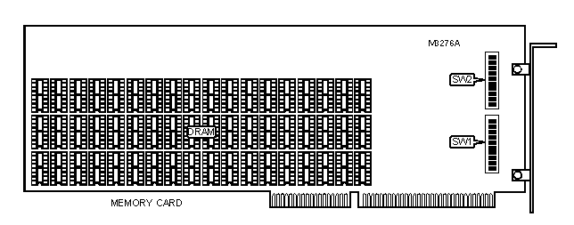
DRAM |
|
Note: The orientation and chip sizes are unidentified. |
|
MEMORY CARD SWITCHES | |||||
|
Expansion cards installed |
SW1/1 |
SW1/2 |
SW1/3 |
SW1/4 |
SW1/5 |
|
1 |
Off |
Off |
Off |
On |
Off |
|
2 |
Off |
Off |
On |
On |
Off |
|
3 |
Off |
On |
Off |
On |
Off |
|
4 |
Off |
On |
On |
On |
Off |
|
5 |
On |
Off |
Off |
On |
Off |
|
MEMORY CARD SWITCHES (CON’T) | |||||
|
Expansion cards installed |
SW1/6 |
SW1/7 |
SW1/8 |
SW1/9 |
SW1/10 |
|
1 |
Off |
Off |
Off |
On |
On |
|
2 |
Off |
Off |
On |
On |
On |
|
3 |
Off |
On |
Off |
On |
On |
|
4 |
Off |
On |
On |
On |
On |
|
5 |
On |
Off |
Off |
On |
On |
|
MEMORY CARD SWITCHES (CON’T) | |||||
|
Expansion cards installed |
SW2/1 |
SW2/2 |
SW2/3 |
SW2/4 |
SW2/5 |
|
1 |
Off |
Off |
On |
Off |
Off |
|
2 |
Off |
On |
Off |
Off |
Off |
|
3 |
Off |
On |
On |
Off |
Off |
|
4 |
On |
Off |
Off |
Off |
Off |
|
5 |
On |
Off |
On |
Off |
Off |
|
MEMORY CARD SWITCHES (CON’T) | |||||
|
Expansion cards installed |
SW2/6 |
SW2/7 |
SW2/8 |
SW2/9 |
SW2/10 |
|
1 |
Off |
Off |
On |
Off |
On |
|
2 |
Off |
On |
Off |
Off |
On |
|
3 |
Off |
On |
On |
Off |
On |
|
4 |
On |
Off |
Off |
Off |
On |
|
5 |
On |
Off |
On |
Off |
On |
|
MISCELLANEOUS TECHNICAL NOTE |
|
The location of pin 1 on all jumpers is unidentified. |