LEADING EDGE PRODUCTS, INC.
MODEL D2
|
Processor |
80286 |
|
Processor Speed |
8/10MHz |
|
Chip Set |
Zymos |
|
Max. onboard DRAM |
1MB |
|
Cache |
None |
|
BIOS |
Leading Edge |
|
Dimensions |
330mm x 330mm |
|
I/O Options |
Floppy drive interface, parallel port, serial port |
|
NPU Options |
80287 |
|
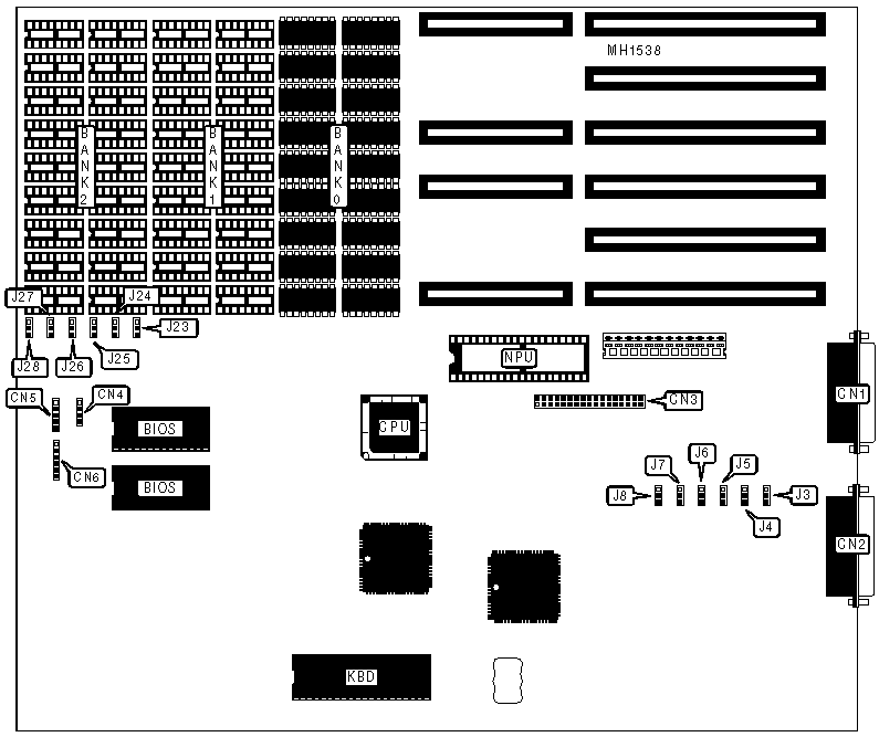
CONNECTIONS | |||
|
Purpose |
Location |
Purpose |
Location |
|
Parallel port |
CN1 |
Speaker |
CN4 |
|
Serial port (25 pin) |
CN2 |
Power LED & keylock |
CN5 |
|
Floppy drive interface |
CN3 |
Keyboard connector |
CN6 |
|
USER CONFIGURABLE SETTINGS | |||
|
Function |
Jumper |
Position | |
| » |
Floppy drive interface enabled |
J7 |
Closed |
|
Floppy drive interface disabled |
J7 |
Open | |
| » |
Floppy drive interface address select primary |
J8 |
pins 2 & 3 closed |
|
Floppy drive interface address select secondary |
J8 |
pins 1 & 2 closed | |
| » |
BIOS select 1 wait state |
J25 |
pins 2 & 3 closed |
|
BIOS select 0 wait states |
J25 |
pins 1 & 2 closed | |
| » |
CPU speed select 10MHz |
J26 |
pins 2 & 3 closed |
|
CPU speed select 8MHz |
J26 |
pins 1 & 2 closed | |
| » |
Monitor type select monochrome |
J27 |
pins 2 & 3 closed |
|
Monitor type select color |
J27 |
pins 1 & 2 closed | |
| » |
Factory configured - do not alter |
J28 |
pins 2 & 3 closed |
|
DRAM CONFIGURATION | |||||
|
Size |
Bank 0 |
Bank 1 |
Bank 2 |
J23 |
J24 |
|
640KB |
(16) 41256 |
(16) 4164 |
NONE |
pins 2 & 3 |
pins 2 & 3 |
|
1024KB |
(16) 41256 |
(16) 41256 |
NONE |
pins 2 & 3 |
pins 1 & 2 |
|
1152KB |
(16) 41256 |
(16) 4164 |
(16) 41256 |
pins 1 & 2 |
pins 2 & 3 |
|
Note:Pins designated should be in the closed position. | |||||
|
SERIAL PORT CONFIGURATION | |||||
|
COM1 |
COM2 |
IRQ |
J5 |
J6 | |
| » |
COM1 |
Disabled |
4 |
pins 1 & 2 closed |
pins 1 & 2 closed |
|
COM1 |
Disabled |
3 |
pins 1 & 2 closed |
pins 2 & 3 closed | |
|
Disabled |
COM2 |
3 |
pins 2 & 3 closed |
pins 2 & 3 closed | |
|
Disabled |
COM2 |
4 |
pins 2 & 3 closed |
pins 1 & 2 closed | |
|
Disabled |
Disabled |
N/A |
pins 1, 2 & 3 closed |
N/A | |
|
PARALLEL PORT CONFIGURATION | |||||
|
LPT1 |
LPT2 |
IRQ |
J3 |
J4 | |
| » |
LPT1 |
Disabled |
7 |
pins 1 & 2 closed |
pins 1 & 2 closed |
|
LPT1 |
Disabled |
5 |
pins 2 & 3 closed |
pins 1 & 2 closed | |
|
Disabled |
LPT2 |
5 |
pins 2 & 3 closed |
pins 2 & 3 closed | |
|
Disabled |
LPT2 |
7 |
pins 1 & 2 closed |
pins 2 & 3 closed | |
|
Disabled |
Disabled |
N/A |
N/A |
pins 1, 2, & 3 closed | |