AMPRO COMPUTERS, INC.
LITTLE BOARD/486I
|
Processor |
80486DX2/80486DX4 |
|
Processor Speed |
50(internal)/100(internal)MHz |
|
Chip Set |
OPTI |
|
Video Chip Set |
Unidentified |
|
Maximum Onboard Memory |
64MB |
|
Maximum Video Memory |
1MB |
|
Cache |
None |
|
BIOS |
Award |
|
Dimensions |
203mm x 146mm |
|
I/O Options |
Ethernet 10BaseT connector, AUI connector, floppy drive interface, IDE interface, SCSI-II interface, parallel port, serial ports (4), VGA interface, flat panel connector, external video overlay, LCD bias supply, PC/104 connectors (2), utility/keyboard connector |
|
NPU Options |
None |
|
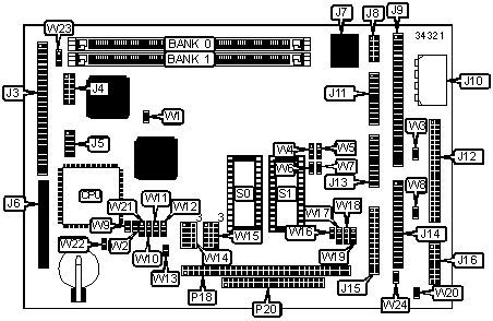
CONNECTIONS | |||
|
Purpose |
Location |
Purpose |
Location |
|
Flat panel connector |
J3 |
Serial port 1 & 2 |
J11 |
|
LCD bias supply |
J4 |
IDE interface |
J12 |
|
VGA interface |
J5 |
Serial port 3 & 4 |
J13 |
|
External video overlay |
J6 |
Floppy drive interface |
J14 |
|
Ethernet 10BaseT connector |
J7 |
Parallel port |
J15 |
|
AUI connector |
J8 |
Utility/keyboard connector |
J16 |
|
SCSI-II interface |
J9 |
PC/104 connector |
P18 |
|
DC power |
J10 |
PC/104 connector |
P20 |
|
Note: Alternate external LAN media are available by means of AUI interface & optional MAUs. | |||
|
USER CONFIGURABLE SETTINGS | |||
|
Function |
Label |
Position | |
|
Negative vee enabled |
W1 |
Pins 1 & 2 closed | |
|
Negative vee disabled |
W1 |
Pins 2 & 3 closed | |
|
» |
Factory configured - do not alter |
W3 |
Unidentified |
|
» |
Factory configured - do not alter |
W8 |
Unidentified |
|
» |
Factory configured - do not alter |
W9 |
Unidentified |
|
» |
Factory configured - do not alter |
W10 |
Unidentified |
|
» |
Factory configured - do not alter |
W11 |
Unidentified |
|
» |
Factory configured - do not alter |
W12 |
Unidentified |
|
» |
Factory configured - do not alter |
W13 |
Unidentified |
|
» |
Factory configured - do not alter |
W16 |
Unidentified |
|
Watch dog timer select IOCHK |
W17 |
Pins 1 & 2 closed | |
|
Watch dog timer select RESET |
W17 |
Pins 2 & 3 closed | |
|
» |
Factory configured - do not alter |
W20 |
Unidentified |
|
» |
Factory configured - do not alter |
W22 |
Unidentified |
|
Low shift clock enabled |
W23 |
Pins 1 & 2 closed | |
|
High shift clock enabled |
W23 |
Pins 2 & 3 closed | |
|
» |
Factory configured - do not alter |
W24 |
Unidentified |
|
DRAM CONFIGURATION | ||
|
Size |
Bank 0 |
Bank 1 |
|
1MB |
(1) 256K x 32 |
None |
|
2MB |
(1) 512K x 32 |
None |
|
2MB |
(1) 256K x 32 |
(1) 256K x 32 |
|
4MB |
(1) 1M x 32 |
None |
|
4MB |
(1) 512K x 32 |
(1) 512K x 32 |
|
8MB |
(1) 2M x 32 |
None |
|
8MB |
(1) 1M x 32 |
(1) 1M x 32 |
|
12MB |
(1) 2M x 32 |
(1) 1M x 32 |
|
16MB |
(1) 4M x 32 |
None |
|
17MB |
(1) 4M x 32 |
(1) 256K x 32 |
|
18MB |
(1) 4M x 32 |
(1) 512K x 32 |
|
20MB |
(1) 4M x 32 |
(1) 1M x 32 |
|
24MB |
(1) 4M x 32 |
(1) 2M x 32 |
|
32MB |
(1) 8M x 32 |
None |
|
32MB |
(1) 8M x 32 |
(1) 4M x 32 |
|
34MB |
(1) 8M x 32 |
(1) 512K x 32 |
|
36MB |
(1) 8M x 32 |
(1) 1M x 32 |
|
40MB |
(1) 8M x 32 |
(1) 2M x 32 |
|
48MB |
(1) 8M x 32 |
(1) 4M x 32 |
|
64MB |
(1) 8M x 32 |
(1) 8M x 32 |
|
VIDEO MEMORY CONFIGURATION |
|
Note: The location of the 512KB/1MB video memory is unidentified. |
|
DMA CHANNEL SELECTION | ||
|
Channel |
W18 |
W19 |
|
1 |
Pins 1 & 2 closed |
Pins 1 & 2 closed |
|
3 |
Pins 2 & 3 closed |
Pins 2 & 3 closed |
|
SERIAL PORT 1 INTERRUPT SELECTION | ||
|
IRQ |
W4 |
W6 |
|
IRQ4 shared with serial 1 |
Pins 1 & 2 closed |
Open |
|
IRQ4 not shared |
Pins 2 & 3 closed |
Closed |
|
SERIAL PORT 2 INTERRUPT SELECTION | ||
|
IRQ |
W5 |
W7 |
|
IRQ3 shared with serial 2 |
Pins 1 & 2 closed |
Open |
|
IRQ3 not shared |
Pins 2 & 3 closed |
Closed |
|
BIOS SELECTION IN S0 & S1 (EPROM) | ||||
|
Type |
W2 |
W14 |
W15 |
W21 |
|
27C64 |
Open |
2 & 5, 7 & 8, 9 & 12, 10 & 11 |
2 & 5, 7 & 8, 9 & 12, 10 & 11 |
2 & 3 |
|
27C128 |
Open |
2 & 5, 7 & 8, 9 & 12, 10 & 11 |
2 & 5, 7 & 8, 9 & 12, 10 & 11 |
2 & 3 |
|
27C256 |
Open |
9 & 12, 14 & 15 |
9 & 12, 14 & 15 |
2 & 3 |
|
27C512 |
Open |
9 & 12, 10 & 11, 14 & 15 |
9 & 12, 10 & 11, 14 & 15 |
2 & 3 |
|
27C010 |
Open |
9 & 12, 10 & 11 |
9 & 12, 10 & 11 |
2 & 3 |
|
27C020 |
Open |
2 & 5, 7 & 8, 9 & 12, 10 & 11 |
2 & 5, 7 & 8, 9 & 12, 10 & 11 |
2 & 3 |
|
27C040 |
Open |
2 & 5, 4 & 7, 9 & 12, 10 & 11, 13 & 14 |
2 & 5, 4 & 7, 9 & 12, 10 & 11, 13 & 14 |
2 & 3 |
|
27C080 |
Open |
4 & 7, 5 & 6, 9 & 12, 10 & 11, 13 & 14 |
4 & 7, 5 & 6, 9 & 12, 10 & 11, 13 & 14 |
2 & 3 |
|
28C64 |
Open |
2 & 5, 7 & 8, 9 & 12, 10 & 11 |
2 & 5, 7 & 8, 9 & 12, 10 & 11 |
2 & 3 |
|
Note: Pins designated should be in the closed position. W14 controls S0 & W15 controls S1. | ||||
|
BIOS SELECTION IN S0 & S1 (FLASH BIOS) | ||||
|
Type |
W2 |
W14 |
W15 |
W21 |
|
29C256 |
Open |
8 & 11, 9 & 12, 14 & 15 |
8 & 11, 9 & 12, 14 & 15 |
2 & 3 |
|
28C256 |
Open |
8 & 9, 11 & 12, 14 & 15 |
8 & 9, 11 & 12, 14 & 15 |
2 & 3 |
|
29F512 |
Open |
4 & 5, 7 & 8, 9 & 12, 10 & 11, 13 & 14 |
4 & 5, 7 & 8, 9 & 12, 10 & 11, 13 & 14 |
2 & 3 |
|
29F010 |
Open |
4 & 5, 7 & 8, 9 & 12, 10 & 11, 13 & 14 |
4 & 5, 7 & 8, 9 & 12, 10 & 11, 13 & 14 |
2 & 3 |
|
29F020 |
Open |
4 & 5, 7 & 8, 9 & 12, 10 & 11, 13 & 14 |
4 & 5, 7 & 8, 9 & 12, 10 & 11, 13 & 14 |
2 & 3 |
|
29F040 |
Open |
4 & 5, 7 & 8, 9 & 12, 10 & 11, 13 & 14 |
4 & 5, 7 & 8, 9 & 12, 10 & 11, 13 & 14 |
2 & 3 |
|
28F512 |
Open |
2 & 5, 7 & 8, 9 & 12, 10 & 11, 13 & 14 |
2 & 5, 7 & 8, 9 & 12, 10 & 11, 13 & 14 |
2 & 3 |
|
28F010 |
Open |
2 & 5, 7 & 8, 9 & 12, 10 & 11, 13 & 14 |
2 & 5, 7 & 8, 9 & 12, 10 & 11, 13 & 14 |
2 & 3 |
|
28F020 |
Open |
2 & 5, 7 & 8, 9 & 12, 10 & 11, 13 & 14 |
2 & 5, 7 & 8, 9 & 12, 10 & 11, 13 & 14 |
2 & 3 |
|
Note: Pins designated should be in the closed position. W14 controls S0 & W15 controls S1. | ||||
|
BIOS SELECTION IN S0 & S1 (SRAM & NOVRAM) | ||||
|
Type |
W2 |
W14 |
W15 |
W21 |
|
BQ4013Y |
Open |
7 & 10, 8 & 9, 11 & 12, 14 & 15 |
7 & 10, 8 & 9, 11 & 12, 14 & 15 |
2 & 3 |
|
BQ4015Y |
Open |
4 & 5, 7 & 10, 8 & 9, 11 & 12, 13 & 14 |
4 & 5, 7 & 10, 8 & 9, 11 & 12, 13 & 14 |
2 & 3 |
|
42356 |
Open |
7 & 10, 8 & 9, 11 & 12, 14 & 15 |
7 & 10, 8 & 9, 11 & 12, 14 & 15 |
2 & 3 |
|
DS1235Y |
Open |
7 & 10, 8 & 9, 11 & 12, 14 & 15 |
7 & 10, 8 & 9, 11 & 12, 14 & 15 |
2 & 3 |
|
DS1650Y |
Open |
4 & 5, 7 & 10, 8 & 9, 11 & 12, 13 & 14 |
4 & 5, 7 & 10, 8 & 9, 11 & 12, 13 & 14 |
2 & 3 |
|
628128 |
Open |
7 & 10, 8 & 9, 11 & 12, 14 & 15 |
7 & 10, 8 & 9, 11 & 12, 14 & 15 |
2 & 3 |
|
628512 |
Open |
4 & 5, 7 & 10, 8 & 9, 11 & 12, 13 & 14 |
4 & 5, 7 & 10, 8 & 9, 11 & 12, 13 & 14 |
2 & 3 |
|
Note: Pins designated should be in the closed position. W14 controls S0 & W15 controls S1. | ||||