TEKRAM TECHNOLOGY CO., LTD.
DC-680, DC-680T
|
| |
|
Data bus: |
32-bit, VL-bus |
|
Size: |
Three/quarter-length, full-height card |
|
Hard drive supported: |
Four IDE (AT) Interface drives |
|
Floppy drives supported: |
Two 360KB, 720KB, 1.2MB, or 1.44MB drives |
|
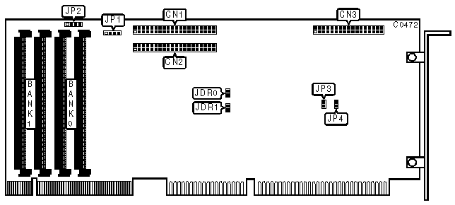
CONNECTIONS | |
|
Function |
Location |
|
40-pin IDE (AT) Interface connector - IDE-0 |
CN1 |
|
40-pin IDE (AT) Interface connector - IDE-1 |
CN2 |
|
34-pin control cable connector - floppy drive |
CN3 |
|
4-pin connector - drive active LED |
JP1 |
|
4-pin connector - cache error speaker |
JP2 |
|
USER CONFIGURABLE SETTINGS | |||
|
Function |
Location |
Setting | |
| » |
IDE-0 damping resistor enabled |
JDR0 |
open |
|
IDE-0 damping resistor disabled |
JDR0 |
closed | |
| » |
IDE-1 damping resistor enabled |
JDR1 |
open |
|
IDE-1 damping resistor disabled |
JDR1 |
closed | |
|
DRIVE ACTIVE LED ERROR CODES (IMMEDIATELY AFTER POWER-UP) | |
|
Status |
Function |
|
One short flash |
No cache DRAM installed |
|
Two short flashes |
CPU error |
|
Three short flashes |
SRAM error |
|
Four short flashes |
Timer error |
|
MISCELLANEOUS TECHNICAL NOTES |
|
Some versions of this board have two 512KB x 8 DRAM chips mounted in place of Bank 0. In such a case the board will work without additional memory. In all other cases a pair of 256KB, 1MB, or 4MB SIMM modules must be installed in Bank 0 for the board to function. Jumpers JP3 and JP4 are factory-configured - do not alter. |