QDI COMPUTER, INC.
QD6580
|
| |
|
Data bus: |
32-bit, VL-bus |
|
Size: |
Three/quarter-length, half-height card |
|
Hard drive supported: |
Two IDE (AT) interface drives |
|
Floppy drives supported: |
Two 360KB, 720KB, 1.2MB or 1.44MB drives |
|
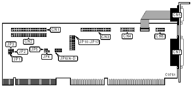
CONNECTIONS | |
|
Function |
Location |
|
40-pin IDE (AT) interface connector - port 1 |
CN1 |
|
40-pin IDE (AT) interface connector - port 1 |
CN2 |
|
34-pin control cabled connector - floppy drive |
CN3 |
|
Game port |
CN4 |
|
9-pin serial port 1 - external |
CN5 |
|
10-pin serial port 2 - internal |
CN6 |
|
25-pin parallel port |
CN7 |
|
2-pin connector - drive active LED |
JPLED |
|
Note:The location of JPLED is not specified in manufacturer’s documentation. | |
|
USER CONFIGURABLE SETTINGS | |||
|
Function |
Location |
Setting | |
| » |
Controls disk peripherals only |
JP1 |
Open |
|
Controls disk and non-disk peripherals |
JP1 |
Closed | |
| » |
Factory configured - do not alter |
JP2 |
pins 2 & 3 closed |
| » |
Chipset register address = 0BXh |
JP4 |
pins 2 & 3 closed |
|
Chipset register address = 03Xh |
JP4 |
pins 1 & 2 closed | |
| » |
Floppy drive enabled |
JP12 |
pins 1 & 2 closed |
|
Floppy drive disabled |
JP12 |
pins 2 & 3 closed | |
| » |
Game port enabled |
JP17 |
pins 1 & 2 closed |
|
Game port disabled |
JP17 |
pins 2 & 3 closed | |
|
IDE PORTS | ||||
|
Port 1 |
Port 2 |
JP3 |
JP5 | |
| » |
Enabled |
Enabled |
pins 2 & 3 closed |
closed |
|
Enabled |
Disabled |
pins 2 & 3 closed |
open | |
|
Disabled |
Disabled |
pins 1 & 2 closed |
n/a | |
|
BIOS ADDRESS - JP6 | |||||
|
Address |
Jumper A |
Jumper B |
Jumper C |
Jumper D | |
| » |
Disabled |
closed |
open |
open |
open |
|
C800h |
open |
closed |
open |
open | |
|
D000h |
open |
open |
closed |
open | |
|
D800h |
open |
open |
open |
closed | |
|
SERIAL PORT 1 CONFIGURATION | |||
|
COM |
JP10 |
JP11 | |
| » |
COM1 |
pins 1 & 2 closed |
pins 1 & 2 closed |
|
COM3 |
pins 1 & 2 closed |
pins 2 & 3 closed | |
|
Disabled |
pins 2 & 3 closed |
pins 1 & 2 closed | |
|
Disabled |
pins 2 & 3 closed |
pins 2 & 3 closed | |
|
SERIAL PORT 2 CONFIGURATION | |||
|
COM |
JP15 |
JP16 | |
| » |
COM2 |
pins 1 & 2 closed |
pins 1 & 2 closed |
|
COM4 |
pins 1 & 2 closed |
pins 2 & 3 closed | |
|
Disabled |
pins 2 & 3 closed |
pins 1 & 2 closed | |
|
Disabled |
pins 2 & 3 closed |
pins 2 & 3 closed | |
|
PARALLEL PORT CONFIGURATION | |||
|
LPT/Address |
JP13 |
JP14 | |
| » |
LPT1/378h |
pins 1 & 2 closed |
pins 1 & 2 closed |
|
LPT2/278h |
pins 1 & 2 closed |
pins 2 & 3 closed | |
|
Disabled |
pins 2 & 3 closed |
pins 1 & 2 closed | |
|
Disabled |
pins 2 & 3 closed |
pins 2 & 3 closed | |