DIAMOND FLOWER, INC.
MIO-2050
|
| |
|
Data bus: |
32-bit VL-bus |
|
Size: |
Three-quarter length, half-height card |
|
Hard drive supported: |
Four IDE(AT) drives |
|
Floppy drives supported: |
Two 360KB, 720KB, 1.2MB, or 1.44MB drives |
|
CONNECTIONS | |
|
Function |
Location |
|
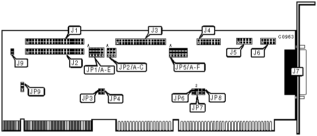
40-pin primary IDE(AT) connector |
J1 |
|
40-pin secondary IDE(AT) connector |
J2 |
|
34-pin cable connector - floppy drive |
J3 |
|
16-pin game port |
J4 |
|
10-pin serial port 1 - internal |
J5 |
|
10-pin serial port 2 - internal |
J6 |
|
25-pin parallel port - external |
J7 |
|
2-pin connector - drive active LED |
J9 |
|
USER CONFIGURABLE SETTINGS | |||
|
Function |
Location |
Setting | |
| » |
IDE(AT) interface enabled |
JP1/A |
Pins 2 & 3 closed |
|
IDE(AT) interface disabled |
JP1/A |
Pins 1 & 2 closed | |
| » |
VLB speed is 50 MHz |
JP1/C |
Pins 2 & 3 closed |
|
VLB speed is 33 MHz |
JP1/C |
Pins 1 & 2 closed | |
| » |
Floppy drive order is normal (A:, B) |
JP2/A |
Pins 2 & 3 closed |
|
Floppy drive order is reversed (B:, A) |
JP2/A |
Pins 1 & 2 closed | |
| » |
Floppy I/O address is 3F0-3F7h |
JP2/B |
Pins 2 & 3 closed |
|
Floppy I/O address is 370-377h |
JP2/B |
Pins 1 & 2 closed | |
|
USER CONFIGURABLE SETTINGS (CONTINUED) | |||
|
Function |
Location |
Setting | |
| » |
Floppy drive interface enabled |
JP2/C |
Pins 2 & 3 closed |
|
Floppy drive interface disabled |
JP2/C |
Pins 1 & 2 closed | |
| » |
Secondary IDE IOCHRDY signal disabled |
JP3 |
Open |
|
Secondary IDE IOCHRDY signal enabled |
JP3 |
Closed | |
| » |
Primary IDE IOCHRDY signal enabled |
JP4 |
Closed |
|
Primary IDE IOCHRDY signal disabled |
JP4 |
Open | |
| » |
Parallel port is uni-directional |
JP6 |
Closed |
|
Parallel port is bi-directional |
JP6 |
Open | |
| » |
Parallel port IRQ 7 select |
JP7 |
Pins 1 & 2 closed |
|
Parallel port IRQ 5 select |
JP7 |
Pins 3 & 4 closed | |
| » |
Game port enabled |
JP8 |
Closed |
|
Game port disabled |
JP8 |
Open | |
|
IDE MODE SELECTION | |||
|
Setting |
JP1/D |
JP1/E | |
| » |
Mode 0 / cycle 600ns |
Pins 2 & 3 closed |
Pins 2 & 3 closed |
|
Mode 1 / cycle 500ns |
Pins 1 & 2 closed |
Pins 2 & 3 closed | |
|
Mode 2 / cycle 400ns |
Pins 2 & 3 closed |
Pins 1 & 2 closed | |
|
Mode 3 / cycle 240ns |
Pins 1 & 2 closed |
Pins 1 & 2 closed | |
|
IDE I/O ADDRESS SELECTION | |||
|
Setting |
JP1/B |
JP9 | |
| » |
IDE I/O address is 170h or 1F0h |
Pins 2 & 3 closed |
Pins 1 & 2 closed |
|
IDE I/O address is 1F0h only |
Pins 1 & 2 closed |
Pins 2 & 3 closed | |
|
PARALLEL PORT ADDRESS SELECTION | |||
|
LPT |
JP5/E |
JP5/F | |
| » |
LPT1 (378h) |
Pins 2 & 3 closed |
Pins 2 & 3 closed |
|
LPT2 (278h) |
Pins 1 & 2 closed |
Pins 1 & 2 closed | |
|
LPT3 (3BCh) |
Pins 1 & 2 closed |
Pins 2 & 3 closed | |
|
Disabled |
Pins 2 & 3 closed |
Pins 1 & 2 closed | |
|
SERIAL PORT 1 ADDRESS SELECTION | |||
|
COM |
JP5/A |
JP5/B | |
| » |
COM1 (3F8h) |
Pins 2 & 3 closed |
Pins 2 & 3 closed |
|
COM3 (3E8h) |
Pins 1 & 2 closed |
Pins 1 & 2 closed | |
|
Disabled |
Pins 1 & 2 closed |
Pins 2 & 3 closed | |
|
SERIAL PORT 2 ADDRESS SELECTION | |||
|
COM |
JP5/C |
JP5/D | |
| » |
COM2 (2F8h) |
Pins 2 & 3 closed |
Pins 2 & 3 closed |
|
COM4 (2E8h) |
Pins 1 & 2 closed |
Pins 1 & 2 closed | |
|
Disabled |
Pins 1 & 2 closed |
Pins 2 & 3 closed | |
|
PARALLEL PORT IRQ SELECTION | |||
|
Setting |
JP7/pins 1 & 2 |
JP7/pins 3 & 4 | |
| » |
IRQ 7 |
Pins 2 & 3 closed |
Pins 1 & 2 closed |
|
IRQ 5 |
Pins 1 & 2 closed |
Pins 2 & 3 closed | |